PCBs are crucial components in battery packs and energy storage systems. The battery PCB protects individual cells, balances charging, monitors performance, and more.
This article will cover everything about the role and specifics of PCBs for lithium batteries in electric vehicles, energy storage, and consumer devices.
What is a Lithium Battery PCB?
A lithium battery PCB is the printed circuit board contained within lithium-ion and lithium polymer battery packs. The PCB houses the battery management system (BMS) and related circuits to control vital battery functionality.
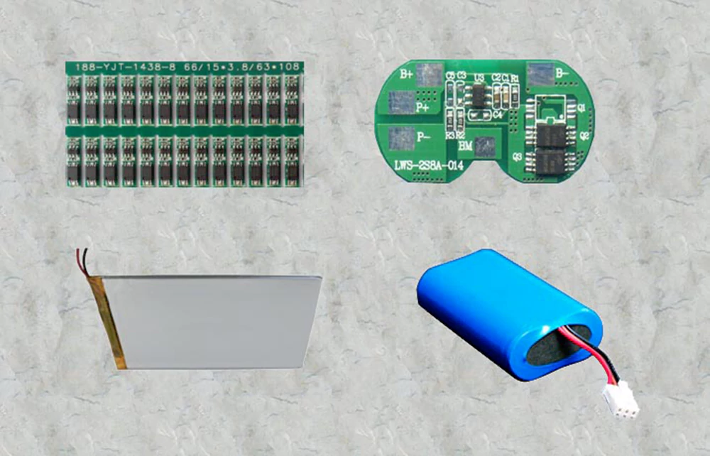
In electric vehicle battery packs, large battery PCBs connect thousands of individual cell pouches or cylindrical cells, balancing their states to maintain pack performance and safety. Smaller PCBs can support just a single 18650 or 26650 cell with basic protection.

What is the PCB in a 18650 Battery?
Cylindrical lithium cells like the 18650 have a small PCB attached to the negative terminal. This simple battery protection PCB prevents overcharging and acts as a fuse if short circuit conditions occur. Materials like aluminum oxide or barium titanium oxide are commonly used.
More advanced battery PCB design integrate the protection board functions together with battery monitoring ICs in a single compact circuit. This saves space and cost versus having separate PCB assemblies.
What is a Battery PCB Protection Board?
A protection board is a critical component on any battery PCB, safeguarding both the battery cells and connected circuitry from damage. Lithium battery cells are vulnerable to operating conditions that degrade performance, reduce lifetime, or pose safety issues if left unmanaged.
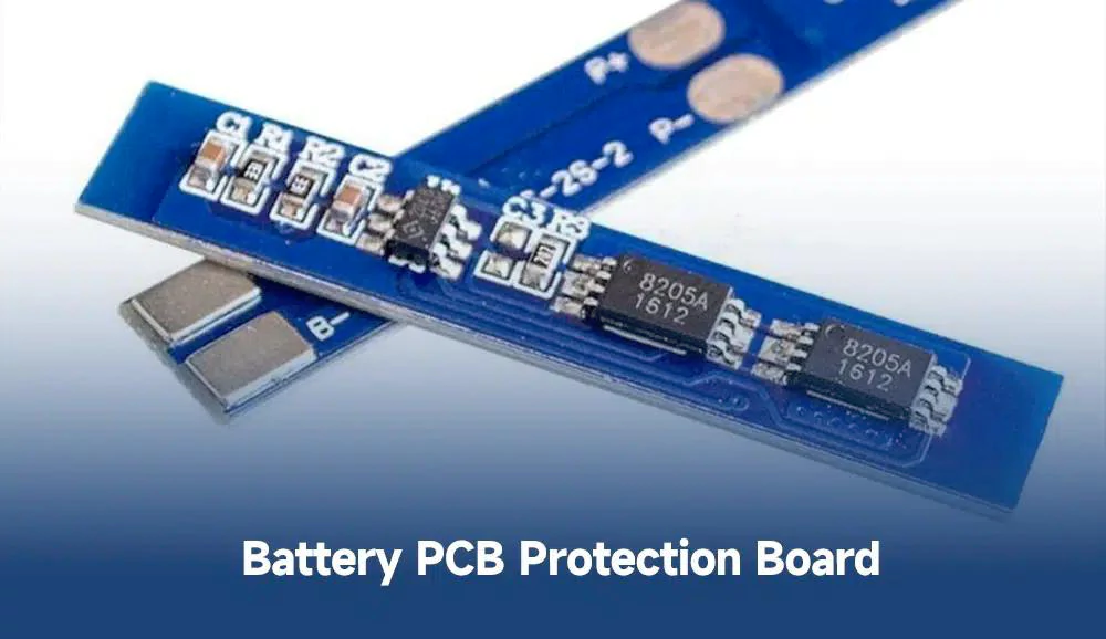
The protection board uses specialized monitoring ICs and control circuitry to continuously measure voltages, currents and temperatures. It takes corrective actions or disconnects the battery when thresholds are exceeded.
Key protection functions include:
Overcharge protection: Disconnects charge current if cell voltage rises over 4.2-4.3V for lithium ion cells. Prevents dangerous buildup of heat or gas.
Over Discharge protection: Opens circuit below 2.0-2.5V to keep cells from being drained beyond safe limits which can permanently damage capacity.
Overcurrent/short circuit protection: Quickly opens connection in overload current or short circuit events up to 45-60A. Protects PCB traces and cells from excessive currents.
Load disconnect: Disconnects battery from application circuitry if out-of-range conditions persist over specified delays. Resets connection only when fault clears.
Cell balancing: Maintains all cells at equal states of charge through passive bleeding resistors or active switching control ICs. Compensates for cell-to-cell capacity differences.
Effective protection PCB designs are vital for reliability, safety and best performance. Without proper safeguards, lithium battery lifespan and reliability would suffer from the many threats cells face in the field.
What is Battery PCB Material?
FR-4 glass epoxy is the most common substrate for simpler battery PCB designs. High-frequency, high-speed or high-power battery applications employ PCB material engineered for better thermal performance like IMS or ceramic substrates.
Conductive layers are typically 1 oz copper foils, sometimes plated with nickel/gold in high reliability battery packs. Lead-free HASL and immersion silver offer environmental-friendly surface finishes.
What are the Features of Battery PCBs?
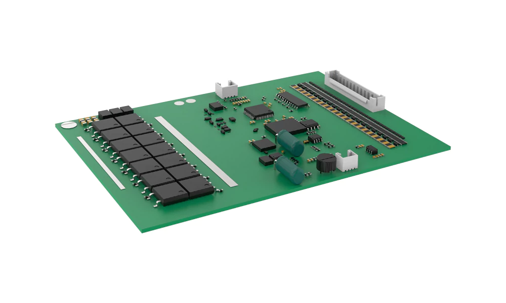
Battery PCB designs incorporate specialized features tailored to the demands of high voltage, high current battery systems:
High current copper traces – Standard 1oz copper can carry over 100A with appropriate conductor sizing. Specialized boards boast up to 20 oz thickness.
Multi-layer stackups – Complex designs employ 6, 8 or even 12+ layers to integrate control circuits with power distribution needs.
Flex-rigid integration – Combines rigid boards to mount components along with flexible bends to withstand vibration/shock.
High-density interconnects – More layers and finer spacing of up to 4 mil lines/spaces. Enables increased component placement.
Mixed voltage domains – Battery PCBs manage voltage transitions for peripheral logic operating at 3.3V/5V along with battery voltage up to 1000V.
Rugged construction – Withstanding vibration, mechanical shock, moisture, dust and temperature extremes (-40°C to +85°C) seen in vehicular and outdoor applications.
Safety certifications – Features like spacing requirements, creepage distances and UL ratings support system level safety sign-offs.
Design for manufacturing (DFM) – To optimize fabrication yields, battery PCB layouts minimize via counts, skipped land patterns, panel utilization concerns and other DFM risks.
Today’s leading battery PCBs leverage both robust base materials and advanced fabrication capabilities to produce designs resilient enough for the toughest battery applications.
What are the Functions of a Battery PCB?
Battery PCBs pack in a wide array of functions critical for battery performance, health, safety monitoring and operational control:
Cell monitoring – ICs continually measure voltage, current and temperature at individual cells and the overall pack to ascertain state. High accuracy (±15-20mV) voltage monitoring required.
Protection circuitry – Detect unsafe or unreliable conditions at the cell level and take action by alerting external controllers or directly controlling contactors.
Cell balancing – Apply charge shuttling or passive bleed resistors to bring overly charged cells down to the level of the lowest cell. Prevents growing mismatches.
Battery management system (BMS) – Process all monitoring data and execute control routines to maximize lifetime, prevent abuse conditions, and maintain safe operating envelopes.
Charge/discharge regulation – Control contactors or DC-DC converters to start/stop charging and load power delivery within specified current and power bands.
Power distribution – Route flows of high current >100A from cells to application loads through thick power planes and bus bars.
Battery pack interconnect – Interfaces between cells, modules, contactors using high density connectors or bussing. Manages wiring complexity.
External interfaces – Implement sensor data acquisition, communication buses like CAN, Bluetooth for battery monitoring apps, and host controllers.
The variety of vital functions integrated into battery PCB designs speaks to their essential roles in battery performance, health and safety.
Battery Management System PCB Design
The complexity of the BMS PCB design depends on the battery application and pack configuration. Large EV and energy storage systems demand intricate PCBs and very rigorous design processes spanning schematic capture, circuit simulation, PCB layout, thermal analysis and design for manufacturing.
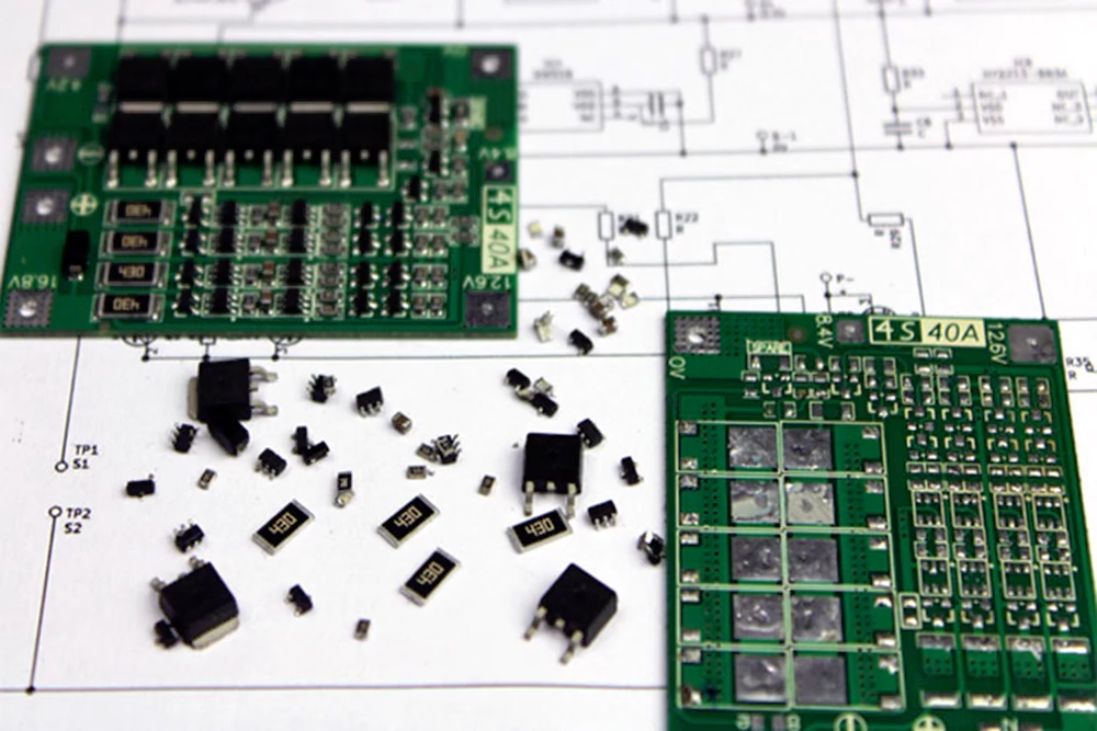
Safety standards compliance and reliability qualification also drive more conservative layout rules beyond commercial PCB guidelines. Multi-board assemblies help manage complex battery wiring in large packs.
How to Choose a Battery PCB Manufacturer?
For prototyping, low volume batch PCB production and rigorous testing, domestic manufacturers provide responsive collaboration and quality assurance. Higher volume production often shifts towards Asian fabricators offering very cost-competitive pricing.
Leading battery PCB manufacturers boast expertise in substrates, high layer counts, and the specialized components involved. Carefully vet potential partners on quality systems, testing capabilities, facilities and production capacities before selecting your preferred battery PCB producer.
Conclusion
Battery protection PCBs have become indispensable to battery performance, safety and pack modularity. Advancements in high-current, high-density PCBs directly support rapid growth in lithium batteries for electric mobility and renewable energy storage adoption. With sound design principles and qualified manufacturing partners, battery systems developers can ensure their PCB technology keeps pace.
A lithium battery PCB is the printed circuit board contained within lithium-ion and lithium polymer battery packs. The PCB houses the battery management system (BMS) and related circuits to control vital battery functionality.
FR-4 glass epoxy is the most common substrate for simpler battery PCB designs. High-frequency, high-speed or high-power battery applications employ PCB materials engineered for better thermal performance like IMS or ceramic substrates.
- High current copper traces
- Multi-layer stackups
- Flex-rigid integration
- High-density interconnects
- Mixed voltage domains
- Rugged construction
- Safety certifications
- Design for manufacturing (DFM)

