The evolution of electronic devices has been marked by a constant quest for innovation and performance. In this pursuit, materials play a pivotal role, and one such material that has garnered significant attention is ceramic. Ceramic Printed Circuit Boards (PCBs) have emerged as a specialized solution, offering a unique set of properties that address the demands of cutting-edge electronic applications.
The article delves into the distinctive characteristics of ceramic PCB, exploring their advantages, applications, and the intricate manufacturing processes that contribute to their significance in the realm of electronic engineering.
How many types of PCB materials are there?
There are several types of materials used in the manufacturing of printed circuit boards (PCBs), and the choice of material depends on the specific requirements of the application. Here are some common types of PCB materials:
FR-4 (Flame Retardant-4): FR-4 is the most widely used material for PCBs. It is a glass-reinforced epoxy laminate with flame-retardant properties. FR-4 is known for its durability, cost-effectiveness, and good electrical insulation properties.
FR-1, FR-2, FR-3: These are older variations of flame-retardant PCB materials, with FR-1 being phenolic paper-based and FR-2 and FR-3 being phenolic cotton-based. They are less common today but may still be used in specific applications.
High-Tg FR-4: High-Tg (glass transition temperature) FR-4 is an enhanced version of FR-4 with a higher Tg value, providing improved heat resistance. This makes it suitable for applications with higher operating temperatures.
Polyimide: Polyimide is a high-temperature-resistant material that can withstand harsh environments. It is often used in flexible PCBs (FPCBs) and rigid-flex PCBs due to its flexibility and thermal stability.
Rogers PCB Materials: Rogers Corporation produces a range of high-performance materials for PCBs, including RO4000 and RO3000 series. These materials are known for their stable electrical properties at high frequencies, making them suitable for RF and microwave applications.
Metal Core PCB (MCPCB): MCPCBs have a metal core (typically aluminum or copper) instead of the traditional epoxy or phenolic substrate. The metal core helps with heat dissipation, making them suitable for applications with high-power components.
Ceramic PCB: Ceramic PCB uses ceramic materials as the substrate, offering excellent thermal conductivity. They are often employed in high-power and high-frequency applications where heat dissipation is critical.
Teflon (PTFE): Teflon-based materials, such as the ones offered by the brand DuPont, are known for their low dielectric constant and loss tangent. They are used in applications where signal integrity and minimal signal loss are crucial, such as in high-frequency RF and microwave circuits.
Nelco PCB Materials: Nelco, a brand under Park Electrochemical Corp., produces PCB materials with specific properties, including low-loss and high-speed materials suitable for high-frequency applications.
What is ceramic PCB?
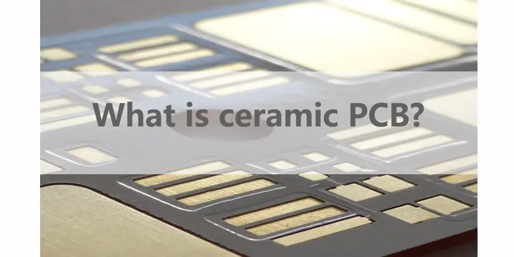
A Ceramic PCB is a type of printed circuit board that uses a ceramic material as the substrate instead of the more common epoxy or fiberglass substrates found in traditional PCBs. Ceramic PCB offers distinct advantages, particularly in applications that require excellent thermal performance, high-frequency operation, and stability in harsh environments.
What are the applications of ceramic PCB?
Ceramic PCB finds applications in various industries where their unique properties, such as high thermal conductivity, stability at high frequencies, and mechanical strength, are advantageous. Here are some common applications of ceramic PCB:
● High-Frequency Electronics: Ceramic PCB is extensively used in high-frequency and RF (Radio Frequency) electronic devices. Their low dielectric constant and low loss tangent make them suitable for applications such as microwave communication systems, radar systems, and high-frequency sensors.
● Power Electronics: Due to their excellent thermal conductivity, ceramic PCB is employed in power electronic devices where efficient heat dissipation is critical. This includes power amplifiers, power supplies, and motor drives.
● LED Technology: Ceramic PCB is utilized in LED (Light Emitting Diode) applications where heat management is crucial. They help dissipate the heat generated by LEDs more effectively, contributing to improved performance and longevity of LED lighting systems.
● Aerospace and Defense: In aerospace and defense applications, ceramic PCB is chosen for their reliability in harsh environments, high-frequency capabilities, and resistance to temperature variations. They are used in communication systems, radar equipment, and electronic components for aircraft and spacecraft.
● Medical Devices: Ceramic PCB is suitable for medical devices where high reliability and precision are essential. They may be used in equipment such as medical imaging devices, diagnostic equipment, and monitoring devices.
● Automotive Electronics: Ceramic PCB is employed in automotive electronics, particularly in components that require high-temperature stability and resistance to thermal cycling. Applications include engine control units (ECUs), power modules, and sensors.
● Wireless Communication Devices: The high-frequency capabilities of ceramic PCB makes them suitable for wireless communication devices, such as smartphones, tablets, and other portable electronic devices. They are used in antennas and RF modules.
● Sensor Technology: Ceramic PCB is utilized in sensors where stability, reliability, and precision are crucial. This includes applications in industrial sensors, environmental monitoring, and scientific instruments.
● High-Power Electronics: In applications requiring high power, such as in industrial equipment and power distribution systems, ceramic PCB is chosen for their ability to handle elevated temperatures and efficiently dissipate heat.
● Electronic Modules for Harsh Environments: Ceramic PCB is preferred in electronic modules designed for harsh environments, including extreme temperatures, vibrations, and corrosive conditions.
What is the advantage and disadvantage of ceramic PCB?
Advantages of Ceramic PCB:
• High Thermal Conductivity:
Ceramic PCB has excellent thermal conductivity, allowing efficient dissipation of heat. This makes them suitable for high-power and high-temperature applications.
• Low Thermal Expansion:
Ceramic materials typically have low thermal expansion coefficients, providing stability under temperature variations. This is beneficial in applications where dimensional stability is crucial.
• High Frequency Performance:
Ceramic substrates have lower dielectric constants, making them suitable for high-frequency applications. They minimize signal loss and interference, making them ideal for RF/microwave circuits.
• Mechanical Rigidity:
While being more brittle, ceramics are mechanically rigid. This rigidity can be advantageous in certain applications where the board needs to maintain its shape and integrity.
• Chemical Resistance:
Advantage: Ceramics are generally more resistant to chemicals compared to some other materials. This can be beneficial in environments where exposure to corrosive substances is a concern.
• Long Lifespan:
Ceramic PCB often has a longer lifespan compared to some alternative materials, contributing to the reliability of electronic devices.
Disadvantages of Ceramic PCB:
• Brittleness:
Ceramic materials are inherently brittle, making them more prone to cracking or breaking under mechanical stress. This can be a limitation in applications where the board may experience significant mechanical forces.
• Cost:
Ceramic PCB is generally more expensive to manufacture compared to alternatives like FR4. The cost of ceramic materials and manufacturing processes contributes to this higher cost.
• Complex Fabrication:
The fabrication of ceramic PCB can be more complex and may require specialized manufacturing processes. This complexity can increase production costs and lead times.
• Limited Flexibility:
Ceramic materials lack the flexibility of some other substrates. This limits their use in applications where a flexible or bendable PCB is required.
• Weight:
Ceramics are denser than some other PCB materials, contributing to a higher weight. In applications where weight is a critical factor, this can be a drawback.
• Not Ideal for Low-Frequency Applications:
While ceramic substrates excel in high-frequency applications, they may not be the best choice for low-frequency circuits due to their lower dielectric constants.
What is the difference between ceramic substrate and FR4?
Ceramic substrate and FR4 are materials commonly used in electronic circuit boards, but they have distinct differences:
Material Composition:
Ceramic Substrate: Made of ceramic materials such as aluminum oxide (Al2O3) or aluminum nitride (AlN). Ceramic substrates offer excellent thermal conductivity.
FR4: FR4 (Fire Retardant 4) is a type of glass-reinforced epoxy laminate. It consists of layers of woven fiberglass cloth impregnated with epoxy resin.
Thermal Conductivity:
Ceramic Substrate: Generally, ceramic substrates have higher thermal conductivity compared to FR4. This property makes them suitable for applications where efficient heat dissipation is critical.
FR4: Has lower thermal conductivity, which may limit its use in high-power and high-temperature applications.
Mechanical Properties:
Ceramic Substrate: Ceramic materials are more brittle and rigid compared to FR4. They may be more susceptible to cracking under mechanical stress.
FR4: Offers better flexibility and is less prone to breakage than ceramic substrates. This makes FR4 boards more durable in certain applications.
Dielectric Constant:
Ceramic Substrate: Typically has a lower dielectric constant compared to FR4. Lower dielectric constant is desirable in high-frequency applications to minimize signal loss.
FR4: Has a higher dielectric constant, which may affect signal integrity in high-frequency circuits.
Cost:
Ceramic Substrate: Generally more expensive than FR4 due to the cost of ceramic materials and manufacturing processes.
FR4: More cost-effective, making it a popular choice for standard PCBs.
Applications:
Ceramic Substrate: Commonly used in high-power electronic devices, RF/microwave applications, and other situations where excellent thermal management is crucial.
FR4: Widely used in general-purpose PCBs for consumer electronics, industrial applications, and low to moderate-power devices.
How are ceramic PCBs made?
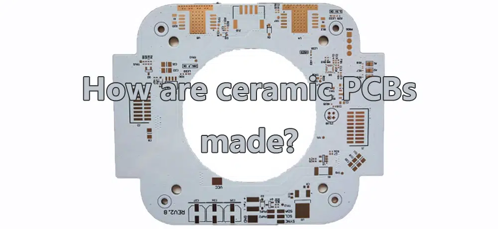
The manufacturing process for ceramic PCBs involves several steps, and it requires specialized equipment and expertise. Here is a general overview of the typical manufacturing process for ceramic printed circuit boards:
Material Selection:
Select the appropriate ceramic material for the PCB based on the specific requirements of the application. Common ceramic materials include aluminum oxide (Al2O3) and aluminum nitride (AlN).
Substrate Preparation:
Cut the ceramic substrate to the desired size and shape using precision cutting tools. The substrate should match the dimensions of the final PCB.
Surface Preparation:
Clean the ceramic substrate thoroughly to remove any contaminants or impurities that could affect the bonding of subsequent layers.
Screen Printing of Conductive Layers:
Use a screen printing process to apply conductive materials, typically metal pastes or inks, onto the ceramic substrate. This forms the conductive traces and pads of the PCB. Multiple layers may be printed to create complex circuit structures.
Drying:
Allow the printed conductive layers to dry completely. This step may involve controlled heating to remove solvents and ensure proper adhesion.
Firing or Sintering:
Subject the substrate to a high-temperature firing or sintering process. This process sinters the metal conductive layers, fusing them to the ceramic substrate. The high temperatures help achieve strong adhesion and conductivity.
Dielectric Layer Application:
Apply a dielectric layer over the fired conductive layers. This dielectric layer serves as insulation between different conductive traces.
Repeat Printing, Drying, and Firing for Additional Layers:
Repeat the screen printing, drying, and firing steps to build up multiple layers of conductive and dielectric materials. The number of layers depends on the complexity of the PCB design.
Via Formation:
Create vias (plated through-holes) to establish electrical connections between different layers. This involves drilling holes through the substrate and depositing conductive material inside the holes.
Surface Finish:
Apply a surface finish to protect the exposed metal surfaces, enhance solderability, and improve overall reliability. Common surface finishes include gold plating or tin/lead coatings.
Component Mounting:
Mount electronic components onto the ceramic PCB using soldering or other appropriate methods. The components are placed on the board according to the design specifications.
Quality Control and Testing:
Perform thorough quality control checks and testing to ensure that the ceramic PCB meets the required specifications. This may include electrical testing, visual inspection, and other testing methods.
Final Finishing:
Cut the PCB into individual boards if necessary and perform any final finishing processes. This may include edge plating or other steps to meet specific design requirements.
What is the thermal conductivity of ceramic PCB?
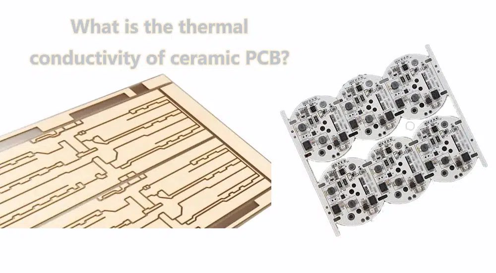
The thermal conductivity of ceramic PCB depends on the specific ceramic material used in their composition. Common ceramic materials used for PCBs include alumina (aluminum oxide, Al2O3) and aluminum nitride (AlN). Here are the typical thermal conductivities for these ceramics:
Alumina (Aluminum Oxide, Al2O3):
The thermal conductivity of alumina is relatively high. It typically ranges from around 20 W/(m·K) to 30 W/(m·K) for different grades and formulations.
This high thermal conductivity makes alumina ceramic PCBs well-suited for applications that require efficient heat dissipation, such as high-power electronic devices and components.
Aluminum Nitride (AlN):
Aluminum nitride also exhibits high thermal conductivity. It generally falls in the range of approximately 170 W/(m·K) to 180 W/(m·K).
AlN is often chosen for applications where both high thermal conductivity and electrical insulation are crucial, such as in high-power and high-frequency electronic devices.
List Ceramic PCB manufacturers
Rogers Corporation:
Website: https://www.rogerscorp.com/
Rogers Corporation is a well-known manufacturer of high-performance materials, including ceramic substrates suitable for advanced electronic applications.
Kyocera Corporation:
Website: https://global.kyocera.com/
Kyocera is a multinational ceramics and electronics manufacturer. They offer a range of ceramic products, including substrates for electronic applications.
CoorsTek:
Website: https://www.coorstek.com/
CoorsTek provides advanced ceramic components, and they are involved in the production of ceramic substrates for electronic and semiconductor applications.
CeramTec:
Website: CeramTec
CeramTec is a global manufacturer of advanced ceramics. They offer various ceramic materials and components, including those used in electronic applications.
Micro Systems Technologies (MST):
Website: https://www.mst.com/
MST is a group of companies specializing in the development and production of microelectronics, including ceramic and LTCC (Low-Temperature Co-fired Ceramic) substrates.
Maruwa Co., Ltd.:
Website: https://www.maruwa-g.com/e/
Maruwa is a Japanese company known for manufacturing ceramic substrates, including those used in the electronics industry.
Anaren (A TTM Technologies Company):
Website: https://www.ttm.com/en
Anaren, now a part of TTM Technologies, offers advanced PCB solutions, including ceramic-based products for RF and microwave applications.
Conclusion
In conclusion, the world of electronic engineering continues to be transformed by innovations in materials and design. Ceramic PCBs, with their exceptional thermal conductivity, low dielectric constants, and mechanical resilience, have etched their place as a crucial component in the development of advanced electronic devices. The journey through the manufacturing process unravels the meticulous steps involved in creating these specialized boards, emphasizing the precision required to harness the unique properties of ceramic materials.
FR-4 (Flame Retardant-4)
FR-1, FR-2, FR-3
High-Tg FR-4
Polyimide
Rogers PCB Materials
Metal Core PCB (MCPCB)
Ceramic PCBs
Teflon (PTFE)
Nelco PCB Materials
A Ceramic Printed Circuit Board (Ceramic PCB) is a type of printed circuit board that uses a ceramic material as the substrate instead of the more common epoxy or fiberglass substrates found in traditional PCBs.
Material Selection
Substrate Preparation
Surface Preparation
Screen Printing of Conductive Layers
Drying
Firing or Sintering
Dielectric Layer Application
Repeat Printing, Drying, and Firing for Additional Layers
Via Formation
Surface Finish
Component Mounting
Quality Control and Testing
Final Finishing

