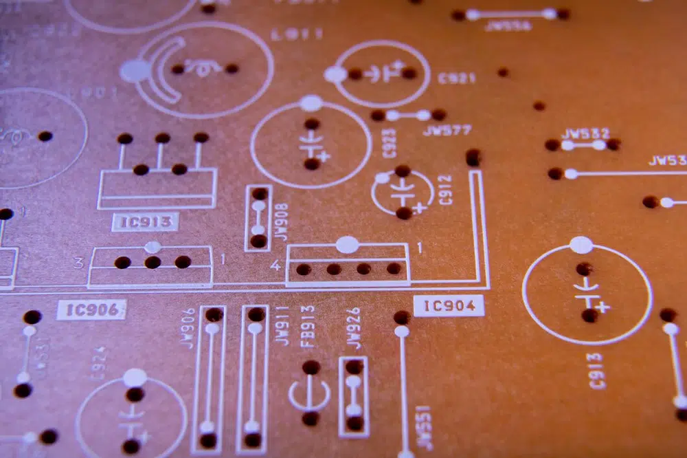
Printed Circuit Boards (PCBs) are integral to modern electronic devices, enabling connectivity and functionality. As technology advances, the demand for higher density and faster signal transmission has led to the adoption of various techniques to enhance PCB performance. One such technique is back drilling, a process used to improve signal integrity and reduce unwanted effects in multilayer PCBs. This article delves into the details of PCB back drilling, its purpose, process, advantages, and considerations.
What is the PCB drilling method?
PCB drilling methods refer to the various techniques used to create holes in printed circuit boards (PCBs) for components, vias, and interconnections. Here are the primary methods:
1. Mechanical Drilling
– Description: Utilizes rotary drill bits to create holes.
– Process: A drill bit rotates at high speed and penetrates the PCB material. This method is commonly used for standard hole sizes.
– Advantages: Cost-effective for mass production; suitable for a wide range of materials.
2. Laser Drilling
– Description: Employs high-energy lasers to vaporize material and create holes.
– Process: The laser beam focuses on specific points, creating precise holes with minimal thermal damage.
– Advantages: Allows for very small holes (down to microvias) and complex geometries; reduces mechanical stress on the board.
3. Microvia Drilling
– Description: Specifically designed for creating microvias used in high-density interconnect (HDI) PCBs.
– Process: Often involves laser drilling or specialized mechanical methods to create very small holes (less than 150 microns).
– Advantages: Supports advanced designs with tight spacing and layer-to-layer connections.
4. Blind and Buried Via Drilling
– Description: Targets vias that do not go through the entire board (blind) or vias that connect internal layers (buried).
– Process: Often requires precise drilling techniques and careful planning in the design phase.
– Advantages: Reduces space usage and enhances electrical performance in multilayer designs.
5. Back Drilling
– Description: A secondary drilling process that removes excess copper from vias.
– Process: Involves drilling from the surface down to a predetermined depth, reducing via length.
– Advantages: Improves signal integrity and reduces inductance and capacitance.
What is a back drill in PCB?
Back drilling, also known as “via back drilling,” is a manufacturing process used to remove excess copper from plated-through holes (vias) in a PCB. This process involves drilling out the section of the via that is not needed for electrical connectivity. It typically targets blind or buried vias, which connect different layers of a multilayer PCB.
What are the purpose of PCB back drilling?
Signal Integrity: Long vias can act as antennas, capturing noise and leading to signal degradation. Back drilling shortens the electrical path, minimizing inductance and capacitance.
Impedance Control: By eliminating unnecessary via length, back drilling helps maintain consistent impedance, crucial for high-speed signal transmission.
Cross-talk Reduction: Reducing the via length decreases the chance of electromagnetic interference between adjacent signals, which is vital in densely packed circuits.
Thermal Management: Shorter vias can help in better thermal dissipation, improving the overall reliability of the PCB.
What is the PCB backdrilling process?
PCB Back drilling is a specialized technique used in the manufacturing of PCBs to improve signal integrity by reducing the length of plated vias. Here’s a detailed overview of the backdrilling process:
Initial Drilling: The PCB is first drilled with standard through holes or vias during the manufacturing process.
Plating: The vias are plated to ensure electrical connectivity between layers.
Back Drilling: A second drilling operation follows, where specialized drill bits remove a portion of the via, usually from the surface layer down to a specified depth. This depth is determined based on the design requirements and electrical specifications.
Inspection: After back drilling, the PCB undergoes inspection to ensure that the drilling depth is accurate and that no damage occurred during the process.
Final Processing: The PCB continues through the remaining manufacturing steps, including solder mask application and surface finishing.
What is the tolerance of a PCB back drill?
The tolerance for PCB back drilling typically ranges from ±0.1 mm to ±0.2 mm (about ±4 mils to ±8 mils). However, the exact tolerance can vary based on several factors, including:
1. PCB Specifications: Different applications may have specific requirements that influence the allowable tolerances.
2. Manufacturer Capabilities: Some manufacturers may offer tighter tolerances depending on their equipment and processes.
3. Via Size and Design: Smaller vias may require tighter tolerances due to the precision needed for effective signal integrity.
4. Drill Bit Size: The size of the drill bits used for back drilling can also affect the achievable tolerance.
Conclusion
Back drilling is a crucial technique in modern PCB manufacturing that enhances signal integrity, reduces unwanted effects, and supports the development of high-density circuits. As electronic devices continue to evolve, the importance of methods like back drilling will only increase, enabling designers and manufacturers to meet the ever-growing demands for performance and reliability. Understanding and implementing back drilling effectively can lead to significant improvements in the functionality and efficiency of PCBs, making it a valuable consideration for engineers and manufacturers alike.
Mechanical Drilling
Laser Drilling
Microvia Drilling
Blind and Buried Via Drilling
Back Drilling
Back drilling, also known as "via back drilling," is a manufacturing process used to remove excess copper from plated-through holes (vias) in a PCB. This process involves drilling out the section of the via that is not needed for electrical connectivity. It typically targets blind or buried vias, which connect different layers of a multilayer PCB.
Initial Drilling
Plating
Back Drilling
Inspection
Final Processing


