Printed Circuit Board (PCB) cable assemblies play a pivotal role in the connectivity and functionality of electronic devices across industries ranging from consumer electronics to aerospace. These assemblies integrate PCB technology with cable harnesses, enabling reliable signal transmission, power distribution, and data communication within complex electronic systems. This article explores the fundamentals of PCB cable assembly, its design considerations and manufacturing processes.
What is PCB Cable Assembly?
PCB cable assembly refers to the integration of printed circuit boards (PCBs) with cables and connectors to facilitate electrical connectivity between different components or subsystems within an electronic device or system. It involves the careful design, selection of components, and assembly techniques to ensure optimal performance, reliability, and durability under various operating conditions.
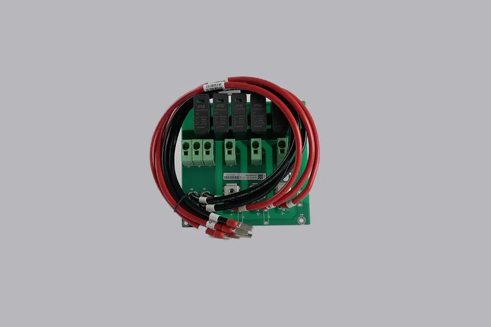
What’s the function of PCB cable assembly?
A PCB cable assembly serves several crucial functions in electronic systems:
1. Electrical Connection: It establishes electrical pathways between different components on a PCB, ensuring signals, power, and data can flow as intended.
2. Signal Transmission: Enables the transfer of signals with minimal loss or interference, maintaining signal integrity across the assembly.
3. Mechanical Support: Provides physical support and stabilization for connectors and cables, reducing stress on solder joints and components.
4. Flexibility and Adaptability: Allows for flexibility in design by accommodating different layouts and configurations within electronic devices.
5. Space Efficiency: Optimizes the use of space on PCBs by integrating connectors and cables neatly into the design, minimizing footprint.
6. Shielding and EMI Protection: Provides shielding against electromagnetic interference (EMI), which can disrupt electronic signals and cause performance issues.
What are the different types of PCB Cable Assembly?
PCB cable assembly encompasss a variety of types and configurations tailored to meet specific application requirements and connectivity needs within electronic systems. Here are some common types of PCB cable assembly:
1. Ribbon Cable Assembly:
Ribbon cable assemblies consist of multiple parallel conductors that are flat and wide, typically arranged in a ribbon-like form. They are often used for internal connections within devices where space is limited and a compact form factor is required.
2. Wire-to-Board Cable Assembly:
These assemblies connect individual wires from a cable to a PCB-mounted connector. The wires are terminated with connectors on one end and soldered or crimped to the PCB on the other end.
3. Board-to-Board Cable Assembly:
Board-to-board cable assemblies connect PCBs to each other, enabling communication and data exchange between different modules or subsystems within a device. They often use specialized connectors that allow for secure and reliable mating between boards.
4. Flat Flexible Cable (FFC) Assembly:
FFC assemblies consist of thin, flat cables with conductors arranged in a flat, parallel layout. They are highly flexible and can be folded or bent to fit into tight spaces or to accommodate complex routing requirements.
5. Custom Cable Assembly:
Custom cable assemblies are designed and manufactured to meet specific requirements of a particular application or device. They may include unique connectors, cable lengths, shielding, and other features tailored to the application’s functional and environmental needs.
6. Coaxial Cable Assembly:
Coaxial cable assemblies consist of a central conductor surrounded by a dielectric insulator, a conductive shield, and an outer insulating jacket. They are designed for high-frequency applications requiring excellent signal integrity and low electromagnetic interference.
7. Harness Cable Assembly:
Harness assemblies involve multiple cables bundled together and terminated with connectors or terminals at both ends. They provide a consolidated and organized approach to connecting multiple points within a system.
8. Overmolded Cable Assembly:
Overmolded assemblies have connectors encapsulated with a molded material (typically plastic or rubber) for strain relief, environmental protection, and enhanced durability. The overmolding process provides a ruggedized solution suitable for harsh environments.
What are the components of PCB cable assembly?
1. PCB:
– PCBs serve as the central platform for mounting electronic components and providing electrical connections between them. They are designed using computer-aided design (CAD) software to layout circuit traces, pads for component mounting, and vias for signal routing.
2. Cables and Wires:
– Cables form the backbone of the assembly, transmitting signals, power, or data between different points on the PCB or to external connectors. They are selected based on factors such as signal integrity requirements, voltage ratings, current carrying capacity, and environmental conditions.
3. Connectors:
– Connectors facilitate the interface between the PCB and external devices or subsystems. They ensure secure mechanical attachment and reliable electrical connection. Connector types vary widely based on application needs, including board-to-board connectors, wire-to-board connectors, and cable-to-board connectors.
4. Backshells and Strain Relief:
– These components provide mechanical support and strain relief for cables and connectors, preventing damage from mechanical stress, vibration, and environmental factors. Backshells also shield against electromagnetic interference (EMI) to maintain signal integrity.
What is the process of PCB cable assembly?
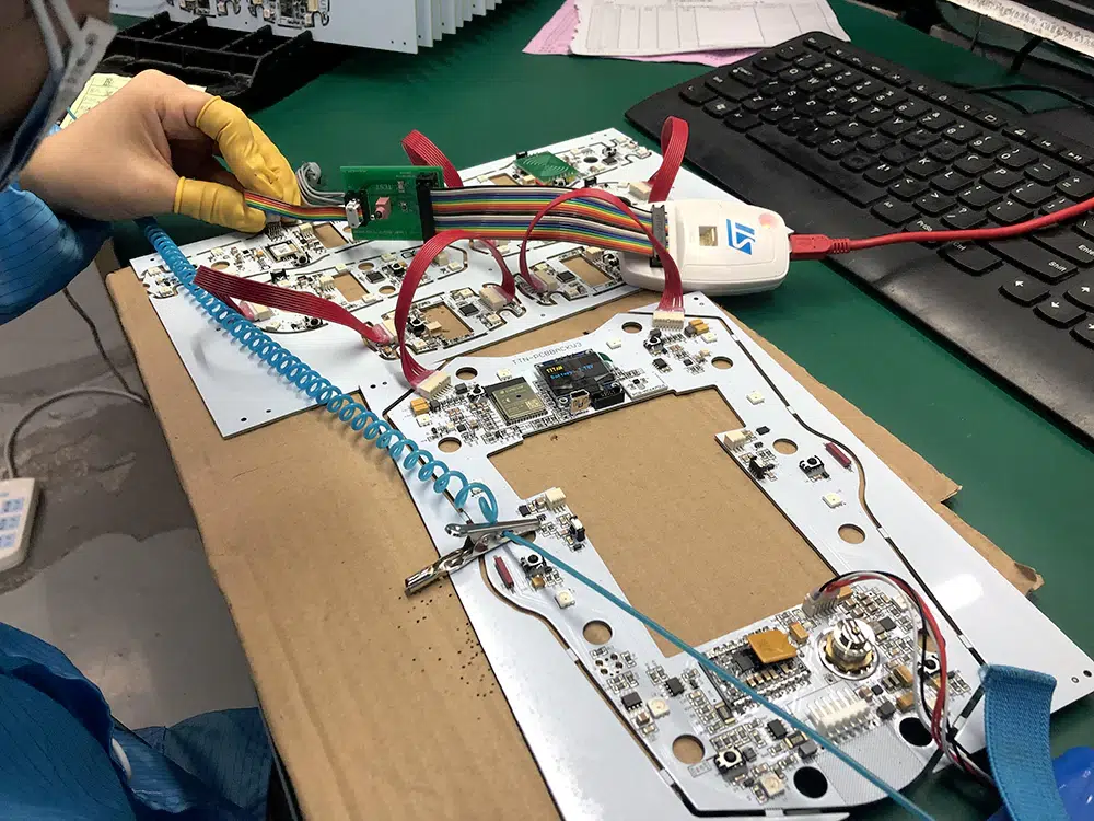
PCB cable assembly involves several manufacturing processes to integrate PCBs, cables, and connectors into a functional assembly:
1. PCB Fabrication:
– PCBs are fabricated using processes such as etching, drilling, and solder mask application to create the required circuit patterns and electrical connections.
2. Component Assembly:
– Surface-mount technology (SMT) and through-hole technology (THT) are used to mount electronic components onto the PCB, including connectors and passive components.
3. Cable Preparation:
– Cables are cut to length, stripped of insulation, and terminated with connectors. Techniques such as crimping, soldering, and insulation displacement are used depending on the type of connectors and cables.
4. Integration and Testing:
– PCBs, cables, and connectors are integrated into the final assembly. Functional testing, continuity testing, and electrical testing (e.g., ICT) ensure that the assembly meets specifications and quality standards.
Design Considerations for PCB Cable Assembly
Designing a PCB cable assembly involves several critical considerations to achieve optimal performance and reliability:
1. Electrical Characteristics:
– Ensure proper impedance matching, signal integrity, and power distribution across the assembly to minimize signal loss, crosstalk, and electromagnetic interference.
2. Mechanical Fit and Form:
– Select connectors and cable lengths that fit within the device enclosure while allowing for easy assembly, maintenance, and serviceability.
3. Environmental and Mechanical Durability:
– Consider the operating environment (temperature, humidity, vibration, shock) to select cables, connectors, and protective coatings that can withstand these conditions without degradation.
4. Assembly and Manufacturing:
– Design for manufacturability (DFM) to simplify assembly processes, reduce labor costs, and minimize potential defects during production.
5. Compliance and Standards:
– Ensure compliance with industry standards (e.g., IPC standards) and regulatory requirements (e.g., RoHS, REACH) for safety, reliability, and environmental protection.
Conclusion
PCB cable assembly combines the precision of PCB technology with the flexibility and functionality of cables and connectors, enabling seamless connectivity and communication within electronic devices and systems. By understanding the design principles, manufacturing processes, and applications of PCB cable assembly, engineers and manufacturers can ensure the delivery of reliable, high-performance solutions that meet the demands of modern technology and industry standards.
PCB cable assembly refers to the integration of printed circuit boards (PCBs) with cables and connectors to facilitate electrical connectivity between different components or subsystems within an electronic device or system.
Electrical Connection
Signal Transmission
Mechanical Support
Space Efficiency
Shielding and EMI Protection
Ribbon Cable Assemblies
Wire-to-Board Cable Assemblies
Board-to-Board Cable Assemblies
Flat Flexible Cable (FFC) Assemblies
Custom Cable Assemblies
Harness Cable Assemblies
...

