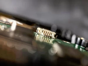
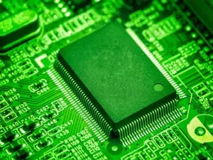
In the intricate world of electronic systems, the role of Printed Circuit Board (PCB) connectors stands paramount. These unassuming components play a crucial role in establishing seamless electrical connections within and between electronic devices, facilitating the transmission of signals, power, and data.
This article aims to delve into the intricacies of PCB connector, exploring their diverse types, applications, and the pivotal role they play in the ever-evolving landscape of electronics.
1. What is a PCB connector?
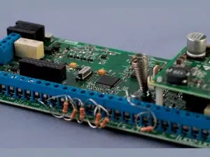
A PCB connector, often simply referred to as a connector, is a device used to establish an electrical connection between a PCB and another electronic component, PCB, or an external device. PCB Connectors are essential components in electronic systems, facilitating the interconnection of various circuit elements. These PCB connector plays a crucial role in enabling the flow of signals, power, and data between different parts of a circuit or between separate electronic systems.
2. How are PCB connectors classified?
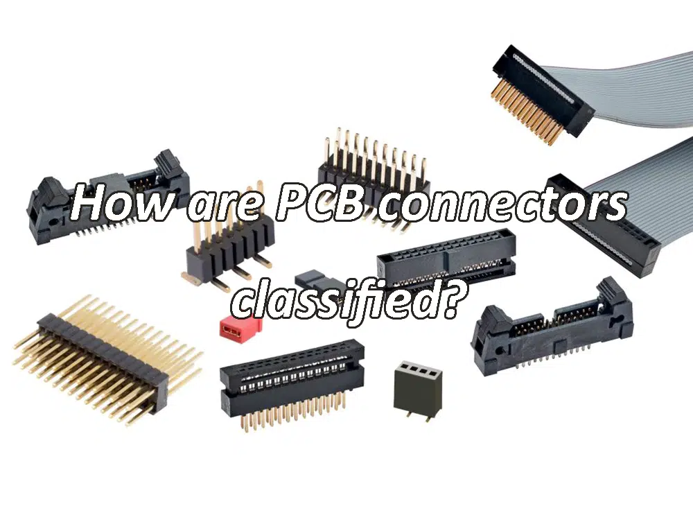
PCB connectors are classified based on various factors, including their design, application, and functionality. The classification helps users select the right connector for specific requirements. Here are common ways PCB connectors are classified:
Connector Type
PCB Connectors are often classified by their specific type, such as:
Headers and Receptacles: Commonly used for board-to-board connections.
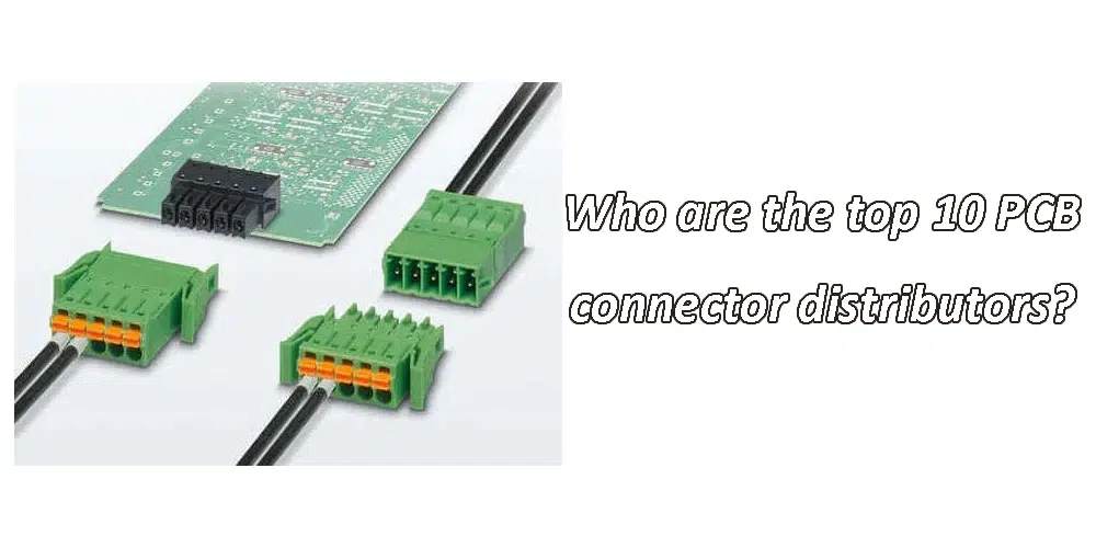
Wire-to-Board Connectors: Designed for connecting wires to a PCB.
Wire-to-Wire Connectors: Used to connect wires directly without a PCB.
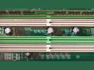
Edge Connectors: Positioned along the edge of a PCB for interfacing with another PCB or device.
Circular Connectors: Have a circular form factor and are used in various applications.
Rectangular Connectors: Have a rectangular shape and come in various sizes and configurations.
Application
PCB Connectors can be classified based on their application, such as:
Power Connectors: Designed for transmitting power between components.
Signal Connectors: Used for transmitting electrical signals.
RF Connectors: Designed for radio frequency applications.
Data Connectors: Used for high-speed data transmission.
Coaxial Connectors: Suitable for coaxial cables and RF applications.
Audio Connectors: Designed for audio signal transmission.
Video Connectors: Used for video signal transmission.
Termination Type
Termination Type:
PCB Connector can be classified based on how they terminate on the PCB, including:
Through-Hole Connectors: Mounted by inserting pins through holes in the PCB.
Surface-Mount Connectors: Attached directly to the surface of the PCB.
Press-Fit Connectors: Pressed into plated-through holes on the PCB without soldering.
Number of Contacts/Pins
PCB Connector can be categorized by the number of contacts or pins they have. For example, connectors can be described as 2-pin, 4-pin, 8-pin, etc.
Gender
Connectors are classified as male or female based on their physical design, with male connectors having protruding pins and female connectors having receptacles to accept those pins.
Pitch
The pitch refers to the distance between adjacent pins or contacts on a connector. Connectors can be classified as having a standard pitch or a high-density pitch.
Mounting Style
Connectors can be classified based on their mounting style, including:
Cable-to-Board Connectors: Connect a cable to a PCB.
Panel-Mount Connectors: Mounted on panels or enclosures.
Specialized Features
Connectors may have specialized features, such as:
Keying or Polarization: Ensures correct alignment during mating.
Locking Mechanisms: Secure connectors in place.
Waterproof Connectors: Designed to resist water ingress.
High-Temperature Connectors: Suitable for applications with elevated temperatures.
Industry Standards
Connectors can be classified based on adherence to industry standards, such as MIL-SPEC connectors or connectors compliant with specific standards like USB, HDMI, etc.
Material and Environmental Specifications
Connectors can be classified based on the materials used and their environmental specifications, such as connectors designed for harsh environments or specific industries.
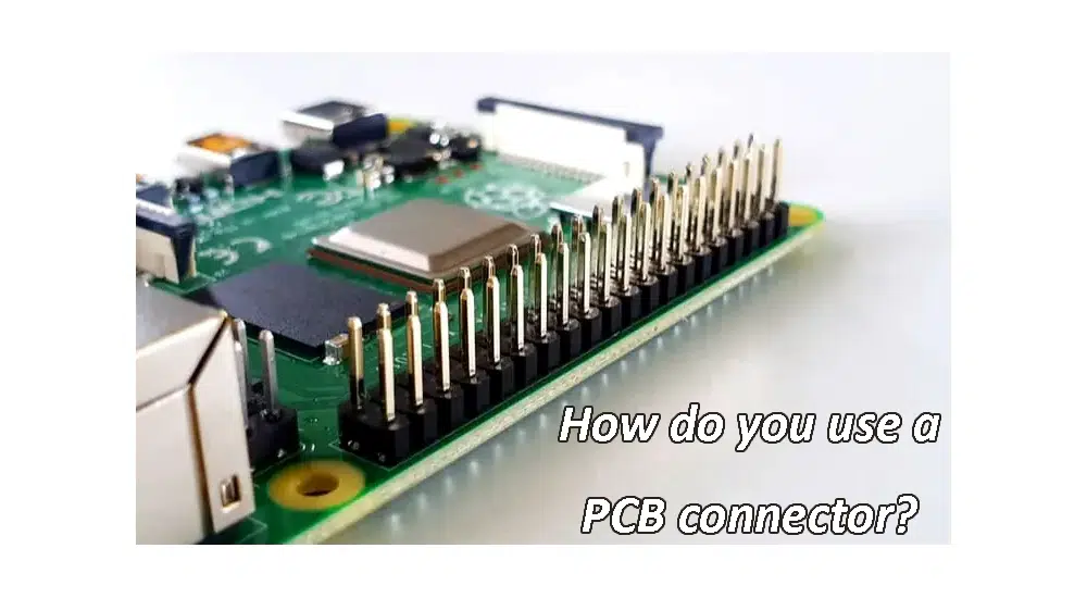
3. How do you use a PCB connector?
Using a PCB connector involves several steps, and the specific process can vary based on the type of connector and its intended application. Here’s a general guide on how to use a PCB connector:
For Board-to-Board Connectors
Identify PCB Connector Type:
Determine the appropriate type of connector for your application (e.g., headers, sockets, or board-to-board connectors).
Prepare PCBs:
Ensure that the PCBs you are connecting have the corresponding footprint or receptacle for the connector.
Place the Connector:
Align the PCB connector with the designated area on the PCB, taking note of any keying or polarization features to ensure proper orientation.
Soldering (if applicable):
If the PCB connector uses through-hole soldering or surface-mount technology (SMT), follow the manufacturer’s guidelines for soldering. Apply heat and solder to secure the connector to the PCB.
Check Alignment:
Verify that the connector is securely mounted and aligned on the PCB.
Mate the Connectors:
If connecting two PCBs, carefully mate the connectors by aligning the pins and sockets. Ensure a firm connection.
Secure the Connection:
Some connectors have locking mechanisms or screws to secure the connection. Use these features if available.
For Wire-to-Board Connectors
Select PCB Connector Type:
Choose the appropriate wire-to-board connector based on your application.
Prepare Wires:
Strip and prepare the wires that will be connected to the connector. Check the manufacturer’s specifications for recommended wire preparation.
Insert Wires:
Insert the prepared wires into the corresponding terminals or sockets of the PCB connector. Follow the numbering or labeling on the connector to ensure correct placement.
Crimp or Solder (if applicable):
Depending on the PCB connector type, crimp the terminals onto the wires or solder them in place.
Secure Strain Relief (if applicable):
If the PCB connector has strain relief features, use them to protect the wires from excessive bending or pulling.
Connect to PCB:
If connecting to a PCB, follow the steps outlined in the “For Board-to-Board Connectors” section.

For Other Connectors
Identify PCB Connector Type:
Understand the specific requirements of the connector type (e.g., edge connector for interfacing with memory cards or expansion cards).
Prepare Mating Device:
Ensure that the mating device (e.g., expansion card) has the corresponding connector that aligns with the PCB edge connector.
Align and Insert:
Align the edge connector on the PCB with the mating connector on the device. Carefully insert the connectors to make electrical contact.
Secure the Connection:
If there are screws or other securing mechanisms, use them to lock the connectors in place.
Check Connection:
Verify that the connection is secure, and there are no misalignments or issues.

4. What are PCB connectors made of?
The components of the PCB connector are: housing, wafer, contacts, terminal and pin.
The plastic shell of the PCB connector has the following functions: supports the contacts (terminals, reeds, etc.) to make them firmly and correctly seated; protects the contacts and conductors from dust, dirt and moisture; insulates the circuits from each other .
wafer is a connector mounted on a printed circuit board.
Contacts The contact part in the connector combines the two parts of conductors (or wires) to be connected. When coupled, the circuit is completed and current flows through the connector.
There are two main types of contact parts: terminals and pins. The specific shapes of physical objects vary greatly. A terminal (or pin) has two ends: a front end and a back end. The front end is always the coupling end, which joins with another terminal to form contact. The rear end always serves as a termination, either for crimping or connecting wires (conductors).
5. What is a pin in a connector?
In the context of a PCB connector, a pin refers to a metal conductor or terminal that is designed to make electrical contact with a corresponding socket, pad, or another pin on a mating connector. These pins are an integral part of the connector and serve as the pathways for electrical signals or power to flow between different components on a printed circuit board (PCB) or between the PCB and external devices.
6. What is a PCB edge connector?
A PCB edge connector, also known simply as an edge connector, is a type of electrical connector designed to connect a printed circuit board (PCB) to another device or component. It is commonly used when the PCB needs to interface with an external system, such as connecting to another PCB, a daughterboard, or an external device like a memory card or expansion card. The distinguishing feature of a PCB edge connector is its location along the edge of the PCB, allowing for easy and secure connections.
7. Who are the top 10 PCB connector distributors?
1. Digi-Key Electronics: Digi-Key is a global distributor providing a wide range of electronic components, including PCB connector.
2. Mouser Electronics: Mouser is another major distributor offering a vast selection of electronic components, including various types of PCB connector.
3. Arrow Electronics: Arrow is a global provider of products, services, and solutions to industrial and commercial users of electronic components and enterprise computing solutions.
4. Avnet: Avnet is a leading distributor of electronic components, including PCB connector, and provides a range of services to design and supply chain professionals.
5. RS Components: RS Components is a global distributor offering a broad range of electronic components, tools, and industrial products.
6. Newark: Newark, an Avnet Company, is a well-known distributor of electronic components and provides a wide selection of connectors.
7. Future Electronics: Future Electronics is a global distributor specializing in electronic components distribution and supply chain solutions.
8. Heilind Electronics: Heilind is a leading distributor of PCB connectors, relays, switches, thermal management, and other electromechanical products.
9. TTI, Inc.: TTI is a leading authorized distributor of interconnect, passive, electromechanical, and discrete components.
10. PEI-Genesis: PEI-Genesis is a global distributor of PCB connector and cable assemblies, specializing in design and assembly services.
Conclusion
From the classic board-to-board connectors to the specialized interfaces designed for high-speed data transmission, the versatility of PCB connectors is a testament to the adaptability required in the ever-changing landscape of technology. As we navigate an era marked by miniaturization, high-speed communication, and relentless innovation, the role of PCB connector remains integral to the success of electronic designs.
In essence, understanding PCB connector is not merely a technical pursuit but a journey into the heart of electronic connectivity. With this newfound knowledge, engineers, designers, and enthusiasts alike are better equipped to navigate the complexities of selecting, implementing, and appreciating the unsung heroes of electronic connections – the PCB connector.
Header Pins and Sockets
Board-to-Board Connectors
Ribbon Cables and Connectors
Wire Harnesses
Flexible PCBs (FPC) or Flex Connectors
Castellated Holes
Wire Jumpers
Edge-to-Edge Connection
Wire Wrapping
A Printed Circuit Board (PCB) connector, often simply referred to as a connector, is a device used to establish an electrical connection between a PCB and another electronic component, PCB, or an external device. Connectors are essential components in electronic systems, facilitating the interconnection of various circuit elements. These connectors play a crucial role in enabling the flow of signals, power, and data between different parts of a circuit or between separate electronic systems.

