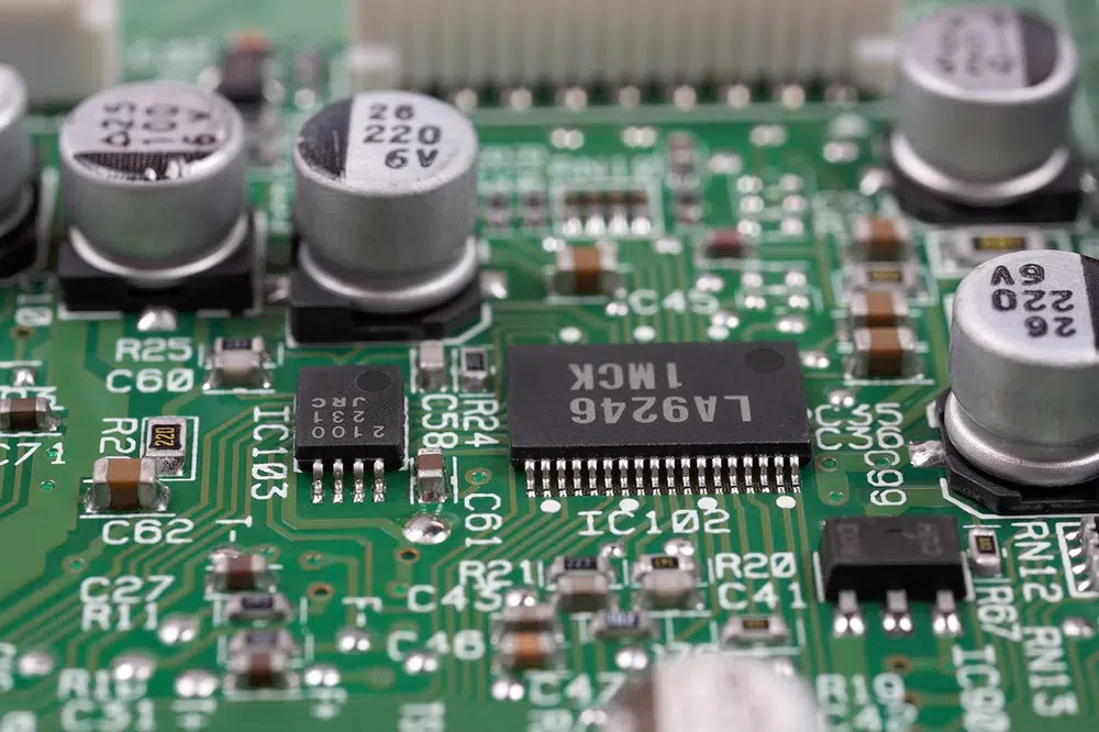
Printed Circuit Board (PCB) sensors have emerged as a pivotal component in the world of electronics, facilitating a wide array of applications in various industries. These sensors are integrated directly onto the PCB, allowing for compact designs, enhanced functionality, and improved performance. With the rise of the Internet of Things (IoT) and smart devices, the demand for efficient, reliable, and versatile sensing solutions, like PCB sensor, has never been higher.
What are PCB sensors?
PCB sensors are devices that detect physical properties (such as temperature, pressure, light, or motion) and convert them into electrical signals. By integrating sensing elements directly onto a PCB, manufacturers can streamline the design, reduce size, and improve the reliability of electronic systems.
What are the types of PCB sensors?
PCB sensors come in various types, each designed to measure specific physical phenomena. Here are some of the main types:
1. Temperature Sensors
– Thermistors: Change resistance with temperature; widely used for precise temperature measurements.
– Thermocouples: Produce a voltage based on temperature differences; suitable for high-temperature applications.
– RTDs (Resistance Temperature Detectors): Use changes in resistance to measure temperature; known for high accuracy.
2. Pressure Sensors
– Piezoelectric Sensors: Generate an electrical charge in response to applied pressure; used in dynamic pressure measurements.
– Strain Gauge Sensors: Measure deformation of a material under pressure; often used in industrial applications.
3. Light Sensors
– Photodiodes: Convert light into electrical current; used in cameras and light-sensing applications.
– Phototransistors: Similar to photodiodes but with amplification; often used in light detection circuits.
4. Motion Sensors
– Accelerometers: Measure acceleration forces; used in smartphones, gaming devices, and automotive applications.
– Gyroscopes: Measure rotational movement; commonly found in drones and navigation systems.
5. Humidity Sensors
– Capacitive Humidity Sensors: Measure humidity by detecting changes in capacitance; widely used in HVAC systems.
– Resistive Humidity Sensors: Change resistance based on moisture levels; often found in consumer electronics.
6. Gas Sensors
– Electrochemical Sensors: Detect specific gases by measuring chemical reactions; commonly used in safety and environmental monitoring.
– MOS (Metal-Oxide-Semiconductor) Sensors: Detect gases based on changes in conductivity; used in various applications, including air quality monitoring.
7. Magnetic Sensors
– Hall Effect Sensors: Detect magnetic fields; often used in position sensing and motor control.
– Magnetoresistive Sensors: Measure magnetic fields based on changes in resistance; used in data storage devices.
8. Distance and Proximity Sensors
– Ultrasonic Sensors: Use sound waves to measure distance; often used in robotics and automotive applications.
– Infrared Sensors: Detect proximity or measure distance using infrared light; used in various automation systems.
What does a sensor do in a PCB board?
A sensor in a PCB (Printed Circuit Board) performs the crucial role of detecting physical phenomena and converting them into electrical signals. Here are the key functions of sensors on PCBs:
1. Data Acquisition: Sensors gather information about environmental conditions, such as temperature, pressure, humidity, light levels, motion, and more.
2. Signal Conversion: They convert physical properties (like heat or light) into electrical signals, making it possible for the PCB to process and analyze the data.
3. Real-Time Monitoring: Sensors enable real-time monitoring of conditions, which is essential for applications like home automation, industrial automation, and medical devices.
4. Feedback Mechanisms: In systems like HVAC or robotics, sensors provide feedback to control systems, allowing them to make adjustments based on current conditions.
5. Enhanced Functionality: By integrating multiple sensors, PCBs can perform complex tasks, such as multi-sensing capabilities, leading to smarter and more efficient devices.
6. Communication: Some sensors can transmit data wirelessly, allowing for remote monitoring and control in IoT applications.
How does PCB sensor work?
PCB sensors work by detecting specific physical properties and converting them into electrical signals that can be processed by electronic circuits. Here’s a breakdown of how they function:
1. Detection Mechanism
– Sensing Element: Each sensor has a sensing element that reacts to the physical phenomenon it is designed to measure, such as temperature, pressure, light, or motion. For example:
– Thermistors change resistance based on temperature.
– Photodiodes generate current in response to light.
2. Signal Conversion
– Transduction: The sensing element converts the detected physical quantity into an electrical signal. This process is known as transduction.
– For instance, in a temperature sensor, a change in temperature alters the resistance, which changes the voltage across the sensor.
3. Signal Conditioning
– Amplification and Filtering: The raw signal from the sensor is often weak and may contain noise. Signal conditioning circuits amplify the signal and filter out unwanted noise, making it suitable for further processing.
4. Analog-to-Digital Conversion (if needed)
– ADC: In many cases, the processed analog signal is converted into a digital signal using an analog-to-digital converter (ADC). This step is essential for interfacing with microcontrollers or digital processing systems.
5. Data Processing
– Microcontroller/Processor: The digital signal is then sent to a microcontroller or processor on the PCB, which interprets the data, performs calculations, and makes decisions based on the sensor input.
6. Output and Communication
– Actuation: Based on the processed data, the system can trigger actions, such as turning on a fan, adjusting a thermostat, or sending alerts.
– Data Transmission: In IoT applications, the data may be transmitted wirelessly to other devices or cloud services for monitoring and analysis.
Example: Temperature Sensor
1. Detection: A thermistor detects temperature changes.
2. Signal Conversion: The thermistor’s resistance changes with temperature, altering the voltage.
3. Signal Conditioning: The voltage is amplified and filtered.
4. ADC: The analog voltage is converted to a digital signal.
5. Data Processing: A microcontroller processes this data to determine if heating is required.
6. Output: If heating is needed, the microcontroller activates the heating element.

How is the sensor mounted to the PCB board?
Mounting sensors to a PCB (Printed Circuit Board) involves several key steps to ensure proper alignment, connection, and functionality. Here’s an overview of the common methods used for mounting sensors on PCBs:
1. Through-Hole Mounting
– Process: In this method, sensors with leads or pins are inserted into holes drilled in the PCB.
– Soldering: The pins are then soldered to pads on the opposite side of the PCB. This method is ideal for larger sensors that require strong mechanical support.
2. Surface Mount Technology (SMT)
– Process: SMT involves placing sensors directly onto the surface of the PCB without the need for holes. The sensors usually have flat contacts.
– Soldering: The sensors are soldered to pads on the surface using reflow soldering techniques, where solder paste is applied and heated to create the connections.
3. Embedment
– Process: Some sensors can be embedded within the layers of the PCB during manufacturing. This involves placing the sensor in the desired layer before the lamination process.
4. Adhesive Bonding
– Process: Some sensors, especially those sensitive to heat, can be attached using specialized adhesives instead of soldering.
5. Mechanical Fastening
– Process: Sensors can be mounted using screws or clips, especially when they need to be easily replaceable or adjustable.
6. Flexible PCB Mounting
– Process: For flexible PCBs, sensors can be mounted using similar techniques, often employing SMT for compact designs.
Conclusion
PCB sensors are integral to modern electronic systems, enabling real-time monitoring and intelligent responses to environmental changes. Their functionality hinges on a combination of physical detection, signal conversion, and data processing, allowing them to serve a wide range of applications across industries.
PCB sensors are devices that detect physical properties (such as temperature, pressure, light, or motion) and convert them into electrical signals.
1. Temperature Sensors
2. Pressure Sensors
3. Light Sensors
4. Motion Sensors
5. Humidity Sensors
6. Gas Sensors
7. Magnetic Sensors
8. Distance and Proximity Sensors
1. Data Acquisition
2. Signal Conversion
3. Real-Time Monitoring
4. Feedback Mechanisms
5. Enhanced Functionality
6. Communication

