In the realm of electronics manufacturing, where precision and reliability are paramount, solder joint plays a crucial role in ensuring the functionality and longevity of printed circuit boards (PCBs). These small yet critical connections are where electronic components are bonded to the conductive traces of a PCB, forming the foundation of virtually every electronic device we rely on today.
What is a soldering joint?
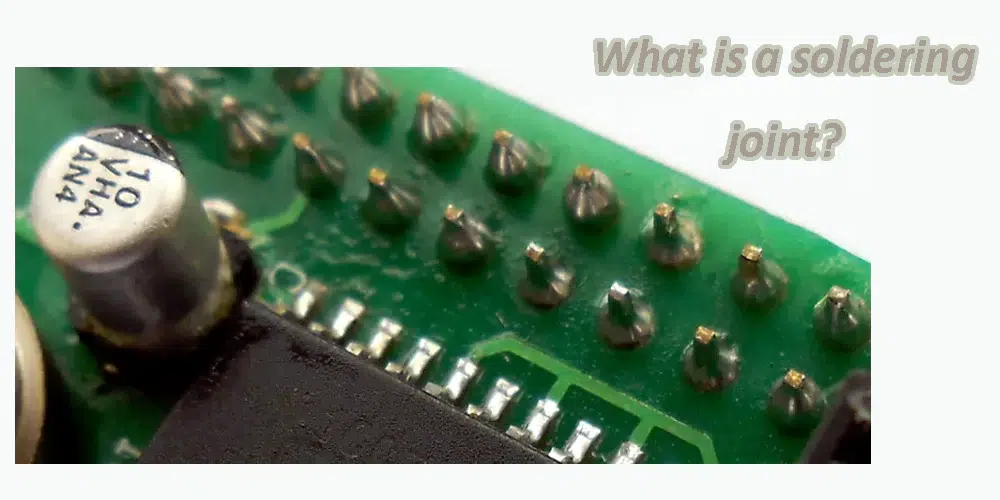
A solder joint is a connection between two or more electrical components or metal parts made using solder. Soldering is a process where a filler metal (solder) is heated above its melting point and then cooled, forming a strong electrical and mechanical bond between the parts being joined.
In electronics and electrical engineering, solder joints are essential for connecting wires to components, attaching electrical components to circuit boards, and creating reliable electrical connections. Soldering joints can vary in complexity and quality depending on factors like the type of solder used, the technique employed, and the materials being joined. Properly made soldering joints are crucial for ensuring electrical conductivity, mechanical stability, and longevity of electronic assemblies.
What are the types of solder joints?
There are several types of solder joints commonly used in electronics and metalwork, each serving different purposes and offering varying levels of strength and reliability. Here are the main types:
*1. Through-Hole Solder Joint: This is used to solder components with wire leads through holes on a printed circuit board (PCB). The solder joint forms on both sides of the PCB, securing the component in place and providing electrical connection.
*2. Surface Mount Solder Joint: This type is used for soldering surface mount components directly onto the surface of a PCB. It involves soldering pads on the PCB and the component leads or pads, creating a connection without the need for holes.
*3. BGA (Ball Grid Array) Solder Joint: BGA components have solder balls on the underside that make contact with pads on the PCB. This type of joint requires precise heating and soldering techniques to ensure all solder balls melt and form reliable connections.
*4. SMD (Surface Mount Device) Solder Joint: Similar to surface mount joints, SMD joints are used for components like resistors, capacitors, and integrated circuits that are directly soldered onto the PCB surface.
*5. Jumper Wire Solder Joint: Sometimes, additional wires (jumper wires) are soldered between PCB pads or components to create connections that aren’t possible with standard traces or to modify existing circuitry.
*6. Wire-to-Wire or Wire-to-Connector Solder Joint: Used in wiring and cable assemblies, where wires or connectors are soldered together to form electrical connections.
Each type of solder joint requires appropriate soldering techniques and equipment to ensure proper bonding and reliable electrical connections. The choice of soldering method depends on the application, the components being used, and the requirements for strength and durability of the joint.
How to make a PCB soldering joint?
Making a proper soldering joint on a PCB is essential for ensuring reliable electrical connections between components and the board. Here’s a step-by-step guide on how to make a soldering joint on a PCB:
Tools and Materials Needed:
2. Solder: Typically a leaded or lead-free solder wire with a flux core.
3. Flux: Optional, but helps in cleaning and improving soldering quality.
4. Sponge or Tip Cleaner: For cleaning the soldering iron tip.
5. PCB: The printed circuit board with components to be soldered
Steps to Make a Soldering Joint:
1. Prepare the Soldering Iron:
– Plug in the soldering iron and allow it to heat up to the appropriate temperature for electronics soldering.
– Clean the soldering iron tip using a damp sponge or brass tip cleaner to ensure it is clean and free of oxidation.
2. Prepare the PCB and Components:
– Place the PCB on a stable surface, ensuring it won’t move during soldering.
– Arrange the components on the PCB according to the circuit diagram.
3. Apply Flux (if necessary):
– Apply a small amount of flux to the areas where components will be soldered. Flux helps in soldering by cleaning the surfaces and promoting solder flow.
4. Heat the Joint:
– Hold the soldering iron in one hand and the solder wire in the other.
– Touch the tip of the soldering iron to the pad/component lead junction. This heats both the pad on the PCB and the component lead.
5. Feed Solder:
– Once the joint is heated sufficiently (typically a couple of seconds), touch the solder wire to the heated joint.
– Allow a small amount of solder to melt onto the joint. The solder should flow evenly and cover the pad and component lead.
6. Remove the Soldering Iron:
– Once the joint is properly soldered (you should see a shiny, smooth fillet), remove the solder wire first, followed by the soldering iron.
– Ensure the soldering iron tip is clean before moving to the next joint.
7. Inspect and Cool:
– Inspect the solder joint visually to ensure it is smooth, shiny, and free from solder bridges or cold joints.
– Allow the solder joint to cool naturally. Avoid moving the board while the solder is still molten to prevent joint failure.
8. Repeat for Other Joints:
– Repeat the above steps for each component lead that requires soldering on the PCB.
Tips for Good Soldering:
– Controlled Heat: Use the right temperature for your soldering iron to avoid overheating components or PCB pads.
– Practice and Patience: Soldering takes practice to perfect. Start with less critical joints if you’re new to soldering.
– Cleanliness: Keep your soldering iron tip clean and tinned (coated with a thin layer of solder) for optimal heat transfer.
– Inspect Joints: Regularly inspect your solder joints to ensure they meet quality standards.
By following these steps and tips, you can create reliable solder joints on your PCB, ensuring good electrical connections for your electronic circuits.
What is bad solder joint?
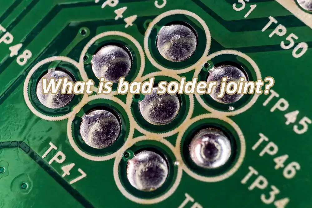
1. Cold Solder Joint: Solder did not properly melt and flow onto the metal surfaces being joined, resulting in poor electrical and mechanical connection.
2. Insufficient Solder: Not enough solder applied to create a strong bond between the components or wires, leading to a weak connection that may break under stress.
3. Solder Bridging: Excessive solder applied that forms unintended connections (bridges) between adjacent pads, traces, or component leads, potentially causing short circuits.
4. Solder Spike: A sharp protrusion of solder that can occur due to excessive solder applied or improper soldering technique, posing a risk of short circuits or mechanical damage.
5. Solder Ball: Small droplets or balls of solder that form unintentionally on the PCB or component leads during soldering, potentially causing electrical shorts or reliability issues.
6. Cracked Solder Joint: Solder joint that has developed cracks due to mechanical stress, thermal cycling, or poor soldering technique, compromising both electrical conductivity and mechanical strength.
7. Brittle Solder Joint: Solder joint that becomes brittle over time due to factors like inadequate flux, improper cooling, or mismatched thermal expansion coefficients, increasing susceptibility to mechanical failure.
8. Incomplete Solder Joint: Areas where the solder did not fully wet or adhere to the metal surfaces, resulting in poor electrical contact or susceptibility to oxidation and corrosion.
9. High Resistance Solder Joint: Solder joint with excessive resistance due to factors like poor wetting, inadequate solder flow, or contamination, leading to electrical performance issues.
10. Tombstoning: Surface mount component lifts up from one end due to unequal heating during soldering, resulting in poor solder joints and potential electrical discontinuity.
Each type of bad solder joint can lead to various operational problems in electronic assemblies, including intermittent connections, reduced electrical performance, or complete failure over time. Proper soldering techniques, adequate equipment, and careful inspection are essential to minimize the occurrence of bad solder joints and ensure the reliability of electronic circuits.
What is a good solder joint?
A well-executed solder joint exhibits several key characteristics:
• Smooth and Shiny Appearance: A properly soldered joint should have a shiny, smooth appearance, indicating that the solder has flowed evenly and formed a strong bond.
• No Solder Bridges: Solder bridges occur when solder unintentionally connects adjacent pads or traces. Good soldering technique minimizes the risk of solder bridges, ensuring proper electrical isolation.
• Sufficient Solder Coverage: The solder should cover both the component lead and the PCB pad adequately, forming a strong mechanical and electrical connection.
• No Cold Joints: Cold joints occur when the solder does not properly bond with the metal surfaces due to insufficient heat or improper technique. Cold joints are weak and can lead to unreliable connections.
How do you check solder joints?
To check solder joints:
1. Visual Inspection: Use magnification to look for smooth, shiny joints with concave fillets. Check for solder bridges, balls, or irregularities.
2. Tactile Inspection: Gently touch joints for stability. A loose joint indicates potential issues.
3. Electrical Testing: Use a multimeter for continuity and resistance checks to ensure proper electrical connections.
4. Mechanical Stress Testing: Apply gentle pressure to assess joint strength.
5. Functional Testing: Power up the circuit to verify proper operation, ensuring solder joints are reliable under working conditions.

How to create a reliable solder joint?
Creating reliable solder joints requires skill, precision, and adherence to best practices:
-• Temperature Control: Use a soldering iron with adjustable temperature settings appropriate for electronics. Excessive heat can damage components or PCBs, while insufficient heat leads to poor solder flow.
-• Flux Application: Flux is used to clean and prepare the metal surfaces for soldering. It helps remove oxidation and contaminants, ensuring a strong solder bond.
-• Soldering Iron Maintenance: Keep the soldering iron tip clean and tinned (coated with solder) to ensure efficient heat transfer and prevent oxidation.
-• Inspection and Quality Assurance: Regularly inspect solder joints visually or using magnification to verify quality. Automated inspection systems are often used in mass production to detect defects such as insufficient solder or solder bridges.
Conclusion
In conclusion, soldering joints are the fundamental building blocks of electronic devices, providing both mechanical support and electrical connectivity in PCB assembly. Understanding the different types of solder joints, their characteristics, and best practices for creating them is essential for producing reliable and high-quality electronic products.
Whether in consumer electronics, telecommunications, automotive systems, or aerospace applications, the importance of well-executed solder joints cannot be overstated—they are the invisible glue that holds our interconnected world together.
A solder joint is a connection between two or more electrical components or metal parts made using solder. Soldering is a process where a filler metal (solder) is heated above its melting point and then cooled, forming a strong electrical and mechanical bond between the parts being joined.
Through-Hole Solder Joint
Surface Mount Solder Joint
BGA (Ball Grid Array) Solder Join
SMD (Surface Mount Device) Solder Joint
Jumper Wire Solder Joint
Wire-to-Wire or Wire-to-Connector Solder Joint
Cold Solder Joint
Insufficient Solder
Solder Bridging
Solder Spike
Solder Ball
Cracked Solder Joint
Brittle Solder Joint
Incomplete Solder Joint
High Resistance Solder Joint

