In the realm of electronics, where precision and reliability are paramount, certain components stand out for their unique characteristics and versatile applications. Among these components, the Zener diodes hold a significant place, revered for its ability to regulate voltage, protect circuits from overvoltage conditions, and serve as a stable voltage reference.
This article serves as an exploration into the fascinating world of Zener diodes, delving into their principles of operation, functions, and the profound impact they have had on modern electronics.
What is Zener diode used for?
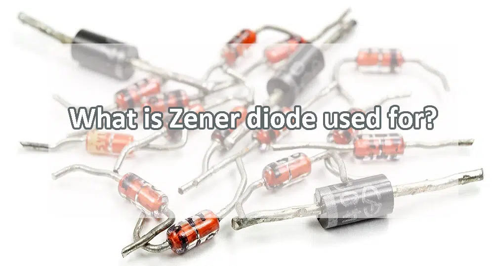
Zener diodes are semiconductor devices that are primarily used for voltage regulation and voltage reference applications in electronic circuits.
Zener diodes are versatile components widely used in various electronic circuits for voltage regulation, voltage reference, overvoltage protection, waveform shaping, and noise suppression purposes. Their ability to maintain a constant voltage across their terminals under reverse bias makes them indispensable in many electronic applications.
Here are some common uses of Zener diodes:
Voltage Regulation: Zener diodes are often used to regulate voltage in electronic circuits. When reverse-biased beyond their breakdown voltage (known as the Zener voltage), they maintain a nearly constant voltage across their terminals, regardless of changes in current flowing through them. This property makes them ideal for stabilizing voltage levels in various applications.
Voltage Reference: Zener diodes can provide a stable reference voltage in electronic circuits. By selecting a Zener diode with a specific breakdown voltage, designers can create a precise reference voltage for use in analog circuits, such as voltage comparators, oscillators, and analog-to-digital converters.
Overvoltage Protection: Zener diodes can be employed in overvoltage protection circuits to safeguard sensitive electronic components from voltage spikes or transients. When the input voltage exceeds the Zener voltage, the Zener diode conducts, shunting excess current away from the protected components and limiting the voltage across them.
Clipping and Clamping Circuits: Zener diodes are used in clipping and clamping circuits to modify the shape of voltage waveforms. In clipping circuits, Zener diodes are used to limit the amplitude of voltage signals by conducting when the voltage exceeds a certain level. In clamping circuits, Zener diodes are used to shift the DC level of a waveform to a desired level.
Voltage Detection: Zener diodes are employed in voltage detection circuits to trigger actions when a specific voltage threshold is reached. For example, they can be used in battery monitoring circuits to indicate when the battery voltage drops below a certain level.
Noise Suppression: Zener diodes can be utilized in noise suppression circuits to limit unwanted voltage fluctuations or spikes in electronic systems. By providing a predictable voltage drop across their terminals, Zener diodes can help stabilize circuit operation in the presence of noise.
How does a Zener diode protect a circuit?
A Zener diode protects a circuit primarily by providing overvoltage protection, which means it limits the voltage across sensitive components or sections of the circuit by conducting excess current when the voltage exceeds a certain threshold known as the Zener voltage. Here’s how a Zener diode protects a circuit:
Voltage Limiting: When the voltage across the Zener diode exceeds its breakdown voltage (Zener voltage), the diode starts conducting heavily in the reverse bias direction. This behavior ensures that the voltage across the diode remains nearly constant at the Zener voltage, effectively limiting the voltage across the protected circuit elements.
Absorption of Excess Energy: In the event of a voltage spike or transient, such as those induced by lightning strikes, electromagnetic interference (EMI), or sudden load changes, the Zener diodes rapidly conduct, diverting excess current away from the protected components. By absorbing this excess energy, Zener diodes prevents the voltage from reaching damaging levels and protects the circuit from potential damage or malfunction.
Clamping Function: In addition to voltage limiting, Zener diodes can also act as voltage clamps. When the voltage exceeds the breakdown voltage, the Zener diode conducts, effectively clamping the voltage across the circuit to the Zener voltage. This clamping action ensures that the voltage does not exceed a safe threshold, protecting downstream components from overvoltage conditions.
Fast Response Time: Zener diodes have a fast response time, allowing them to respond quickly to voltage fluctuations or spikes in the circuit. This rapid response helps minimize the duration of overvoltage conditions and prevents prolonged exposure of sensitive components to high voltages.
Robustness: Zener diodes are designed to withstand high levels of reverse bias voltage without being damaged. This robustness ensures that they can effectively protect the circuit under adverse conditions, such as voltage surges or transient events.
How are Zener diodes formed?
Zener diodes are formed using a process known as doping, which involves introducing specific impurities into semiconductor materials to modify their electrical properties. Here’s how Zener diodes are typically formed:
Selection of Semiconductor Material: Zener diodes are commonly made from silicon (Si) or germanium (Ge) semiconductor materials due to their favorable electrical properties. Silicon is more widely used due to its higher operating temperature and better stability.
Crystal Growth: The semiconductor material is grown into a single crystal using methods such as the Czochralski process or the float-zone technique. This process ensures high purity and uniformity of the semiconductor material.
Doping: Once the semiconductor crystal is grown, it undergoes doping to introduce impurities into specific regions. Zener diodes are typically formed from p-n junctions, where one side of the junction is heavily doped with acceptor impurities (p-type) and the other side is heavily doped with donor impurities (n-type).
Formation of the p-n Junction: The heavily doped n-type and p-type regions are brought into contact to form the p-n junction, which is the basis of the Zener diode. The interface between the n-type and p-type regions forms a depletion region, which is essentially a region depleted of free charge carriers.
Breakdown Voltage Adjustment: To achieve the desired breakdown voltage (Zener voltage), the doping levels and geometry of the p-n junction are carefully controlled during the manufacturing process. Higher doping levels result in lower breakdown voltages, while larger depletion regions lead to higher breakdown voltages.
Encapsulation: Once the p-n junction is formed and the breakdown voltage is set, the Zener diode is encapsulated in a protective package to provide mechanical support and environmental protection. The package also provides electrical contacts for connecting the diode to external circuits.
Testing and Quality Control: After encapsulation, the Zener diodes undergo rigorous testing to ensure that they meet specified electrical characteristics, such as breakdown voltage, reverse leakage current, and dynamic resistance. Quality control measures are implemented to ensure consistent performance and reliability of the Zener diodes.
What is the voltage of a Zener diode?
The voltage of a Zener diode, often referred to as the Zener voltage or breakdown voltage, varies depending on the specific Zener diode part number and its intended application. Zener diodes are manufactured with a wide range of breakdown voltages to suit different circuit requirements.
Common Zener voltages range from a few volts to several hundred volts. Some typical values include 3.3V, 5.1V, 12V, 24V, 48V, etc. These values represent the voltage at which the Zener diode begins to conduct significantly in the reverse bias direction.
When selecting a Zener diode for a particular application, it’s essential to choose one with a breakdown voltage that meets the circuit’s requirements. Additionally, Zener diodes are available with both standard and precise tolerances on their breakdown voltage. For critical applications where precise voltage regulation is necessary, Zener diodes with tighter tolerance specifications are often used.
Ultimately, the specific voltage of a Zener diode depends on its design, manufacturing process, and intended application. It’s essential to consult the datasheet or specifications provided by the manufacturer to determine the breakdown voltage of a particular Zener diode part number.
How do you test a Zener diode?
Testing a Zener diode typically involves verifying its forward and reverse characteristics to ensure it is functioning properly. Here’s how you can test a Zener diode using a multimeter:
Set the Multimeter: First, set your multimeter to the diode test mode (often denoted by a diode symbol or the letters “DIODE” on the selector dial). If your multimeter does not have a specific diode test mode, you can use the continuity mode.
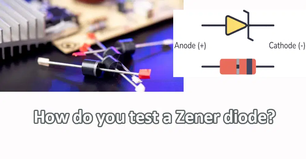
Identify the Anode and Cathode: Determine which terminal of the Zener diode is the anode (positive) and which is the cathode (negative). You can refer to the datasheet or look for markings such as a band, notch, or arrow on the diode, indicating the cathode. Alternatively, use a multimeter in continuity mode to identify the cathode (the terminal with lower resistance when forward-biased).
Forward Bias Test: Connect the positive (red) probe of the multimeter to the anode of the Zener diode and the negative (black) probe to the cathode. You should observe a forward voltage drop across the diode, typically around 0.6 to 0.7 volts for silicon diodes. If the diode does not conduct in the forward direction (open circuit), it may be defective.
Reverse Bias Test: Next, reverse the connections of the multimeter probes, with the positive probe now connected to the cathode and the negative probe to the anode. In this reverse bias configuration, you should observe a high resistance or an open circuit. If the multimeter displays a low resistance or continuity in the reverse direction, the Zener diode may be shorted and defective.
Measure Zener Voltage: If you have a multimeter with a diode test mode, you can also measure the Zener voltage directly by connecting the positive probe to the anode and the negative probe to the cathode. The multimeter will display the voltage drop across the diode, which should be close to the specified Zener voltage. Keep in mind that this method is less accurate than using a dedicated Zener voltage tester.
Compare with Specifications: Compare the measured values with the specifications provided in the Zener diode’s datasheet. Ensure that the forward voltage drop is within the expected range, and the reverse resistance is sufficiently high. If the measured values deviate significantly from the specifications, the Zener diode may be defective and should be replaced.
How do you know if a Zener diode is positive or negative?
Zener diodes, like other semiconductor diodes, have a polarity, meaning they have a positive and a negative terminal. Here’s how you can determine the polarity of a Zener diode:
Identification Markings: Many Zener diodes are marked with identification codes or symbols that indicate their polarity and other specifications. Common markings include a band around one end of the diode or an arrow pointing towards the cathode (negative terminal). Check the datasheet or manufacturer’s documentation for details on interpreting these markings.
Cathode Band: In through-hole Zener diodes, one end of the diode typically has a colored band or a notch to denote the cathode (negative terminal). The cathode end is usually marked with a bar or arrow symbol in the schematic diagram. If you see a band or notch on one end of the diode, that end is the cathode.
Datasheet Information: Refer to the datasheet or specification sheet of the Zener diode for information on its polarity. The datasheet will typically provide details on the pinout, indicating which terminal is the cathode and which is the anode.
Testing with a Multimeter: You can use a multimeter set to the diode test mode to determine the polarity of a Zener diode. Connect the positive probe of the multimeter to one terminal of the diode and the negative probe to the other terminal. If the diode conducts (indicated by a forward voltage drop), the terminal connected to the positive probe is the anode, and the other terminal is the cathode.
Physical Inspection: In surface-mount Zener diodes, the cathode terminal is often marked with a line, dot, or other symbol. This marking may be visible on the top surface of the diode or indicated in the datasheet.
Conclusion
In conclusion, the Zener diodes stand as a cornerstone of modern electronics, offering unparalleled voltage regulation, overvoltage protection, and voltage reference capabilities. From its humble beginnings to its widespread adoption in a myriad of applications, the Zener diodes continue to shape the landscape of electronics engineering.
Its ability to maintain a stable voltage across its terminals, even in the face of fluctuating conditions, makes it an indispensable component in countless circuits, ranging from power supplies and voltage regulators to signal conditioning and sensor interfacing.
Zener diodes are semiconductor devices that are primarily used for voltage regulation and voltage reference applications in electronic circuits.
Voltage Regulation
Voltage Reference
Overvoltage Protection
Clipping and Clamping Circuits
Voltage Detection
Noise Suppression
The voltage of a Zener diode, often referred to as the Zener voltage or breakdown voltage, varies depending on the specific Zener diode part number and its intended application. Zener diodes are manufactured with a wide range of breakdown voltages to suit different circuit requirements.

