In the realm of electronics manufacturing, through hole assembly stands as a foundational technique, offering robustness and reliability in an increasingly miniaturized world dominated by surface-mount technology (SMT). This method involves inserting component leads through drilled holes on a printed circuit board (PCB) and soldering them on the opposite side, ensuring secure mechanical and electrical connections.
Historically, through hole assembly was a predominantly manual process, where skilled technicians carefully placed components and soldered them by hand. However, with advancements in automation technology, especially in selective soldering machines and wave soldering techniques, much of the assembly process can now be automated. This shift has improved efficiency, reduced labor costs, and enhanced consistency in soldering quality.
What is through hole assembly?
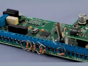
Through hole assembly is a method used in electronics manufacturing to mount components onto printed circuit boards (PCBs). It involves inserting component leads, which are typically formed wires extending from the body of the component, through holes drilled into the PCB. These leads are then soldered to pads on the opposite side of the board to create an electrical and mechanical connection.
Through hole assembly provides strong mechanical support and reliability, making it suitable for components that require robustness against mechanical stress or environmental factors. While it has been largely supplanted by surface-mount technology (SMT) for compact and high-density applications, through hole assembly remains essential for certain types of components and specialized applications where durability and mechanical strength are critical.
What are the advantages and disadvantages of through hole technology?
Through hole technology (THT) in electronics assembly offers both advantages and disadvantages:
Advantages:
1. Mechanical Strength: Components are mounted securely through holes in the PCB, providing robust mechanical support.
2. Reliability: THT is known for its durability and resistance to mechanical stress, making it suitable for harsh environments.
3. Repairability: Components can be easily replaced or repaired by desoldering and resoldering through-hole connections.
4. Heat Dissipation: THT components can dissipate heat better than surface-mount devices (SMDs), as they often have larger physical sizes and contact areas.
Disadvantages:
1. Size and Weight: THT components are generally larger and heavier compared to SMDs, which can limit miniaturization of PCBs.
2. Labor Intensive: Manual insertion and soldering of THT components can be more time-consuming and costly compared to automated SMD assembly processes.
3. Signal Integrity: Longer leads and larger pad sizes in THT can lead to higher parasitic capacitance and inductance, potentially affecting signal integrity at high frequencies.
4. Design Constraints: THT components may require more space on the PCB, limiting the design flexibility and density achievable compared to SMDs.
Where is through hole assembly used?
Through hole assembly (THT) is still widely used in various applications where its specific advantages are beneficial. Here are some common scenarios:
PCB Prototyping and Small-scale Production: For prototyping or low-volume production runs, through hole assembly offers advantages in terms of ease of assembly and repair. It allows for easier manual soldering and component placement, making it suitable for initial testing and development phases.
Mechanical Strength Requirements: When mechanical strength and durability are critical, through hole assembly provides a more robust connection between the components and the PCB. This makes it suitable for applications subject to mechanical stress, vibration, or thermal cycling, such as in industrial equipment, automotive electronics, and military systems.
High Power Applications: Components that handle high currents or require efficient heat dissipation benefit from through hole assembly. The larger leads and metal bodies of through hole components can better dissipate heat compared to their surface-mount counterparts.
Availability of Through Hole Components: Some specialized or legacy components are only available in through-hole packages. Designers may choose through hole assembly to incorporate these specific components into their designs or for repairs where exact replacements are necessary.
How to assemble through-hole components?
* 1.PCB Fabrication or semi-finished the PCB assembly.
* 2. Component Placement: Through-hole components are selected based on the design requirements and availability. These components have leads or wires that are designed to fit through holes drilled in the PCB. During component placement:
– Each component lead is aligned with its corresponding hole on the PCB.
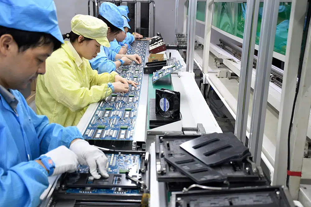
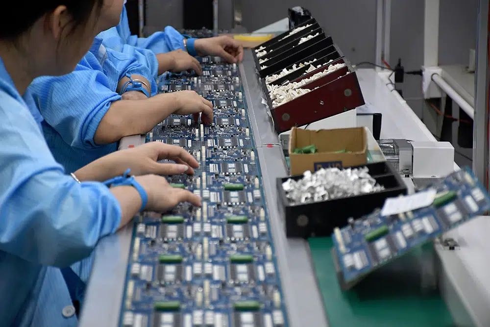
* 3. Insertion: Once components are placed, their leads are inserted through the drilled holes in the PCB. This step can be done manually for prototyping or small-scale production, or automatically in larger-scale production using pick-and-place machines.
* 4. Wave Soldering or Manual Soldering:
– Manual Soldering: For prototypes, repairs, or when wave soldering is not feasible, components are soldered manually. A soldering iron or soldering station is used to apply solder to each lead on the component side of the PCB. Excess solder is removed using desoldering tools if necessary.
* 5. Cleaning: After soldering, the PCB may undergo cleaning to remove flux residues and contaminants left over from the soldering process.
* 6. Inspection: Visual inspection or automated inspection systems are used to check the quality of solder joints and verify that components are properly mounted and soldered.
* 7. Testing: Once assembly and inspection are complete, the PCB may undergo functional testing to ensure that all components operate correctly and meet design specifications.
What is the difference between SMT and THT?
Surface-mount technology (SMT) and through hole technology (THT) are two primary methods for assembling electronic components onto printed circuit boards (PCBs). Here are the key differences between SMT and THT:
Surface-Mount Technology (SMT):
1. Component Mounting: SMT components are mounted directly onto the surface of the PCB, where they are soldered onto pads (flat metal contacts) on the board’s surface.
2. Component Size: SMT components are typically smaller and lighter than through-hole components because they do not have leads extending through the board.
3. Assembly Process: SMT assembly is highly automated using pick-and-place machines that precisely position components onto the PCB. This automated process allows for high-speed assembly and is well-suited for high-volume production.
4. Advantages: SMT offers several advantages including smaller PCB size, higher component density, better high-frequency performance (less parasitic inductance and capacitance), and suitability for automated assembly.
5. Disadvantages: SMT components can be more difficult to solder manually due to their small size and close pad spacing. They may also have lower mechanical strength compared to through-hole components.
Through-Hole Technology (THT):
1. Component Mounting: THT components have leads that extend through holes (plated through-holes) in the PCB. The leads are then soldered to pads on the opposite side of the board.
2. Component Size: THT components are generally larger and heavier than SMT components because they have leads and require holes for mounting.
3. Assembly Process: THT assembly can be manual, semi-automated, or automated depending on the production volume and complexity. Manual soldering and insertion are common for prototype and low-volume production.
4. Advantages: THT offers advantages such as strong mechanical connections (suitable for rugged environments), ease of soldering and rework (components can be easily replaced), and better heat dissipation capability.
5. Disadvantages: THT requires more board space due to the need for holes, limiting PCB design flexibility and density. It is also generally slower and more labor-intensive compared to SMT for high-volume production.
Summary:
In essence, SMT is favored for its compact size, high component density, and automated assembly capabilities, making it ideal for modern electronics where miniaturization and high production throughput are crucial. On the other hand, THT remains valuable for applications requiring robustness, repairability, and where specific component characteristics (such as heat dissipation or mechanical strength) are critical. The choice between SMT and THT depends on factors such as application requirements, production volume, cost considerations, and the specific characteristics of the electronic product being developed.
What are through hole components?
1. Resistors: Through hole resistors have wire leads that are inserted through holes in the PCB and soldered to pads on the other side. They come in various shapes and sizes depending on their power rating and resistance value.
2. Capacitors: Through hole capacitors typically have wire leads or radial leads (leads extending from the sides) that are inserted through holes in the PCB. They are soldered to pads on the opposite side to form electrical connections.
3. Diodes: Through hole diodes have leads that are inserted through holes in the PCB and soldered to pads. They allow current to flow in one direction only and are used for rectification and switching purposes.
4. Transistors: Through hole transistors have three leads (collector, emitter, and base for bipolar junction transistors) or more (for field-effect transistors) that are inserted through holes in the PCB and soldered to pads. They are used for amplification and switching.
5. Integrated Circuits (ICs): Through hole ICs have multiple leads (pins) that are inserted through holes in the PCB and soldered to pads. They include microcontrollers, operational amplifiers, and various other types of analog and digital ICs.
6. Inductors: Through hole inductors have wire leads that are inserted through holes in the PCB and soldered to pads. They are used to store energy in magnetic fields and are essential in various circuit applications.
7. Connectors: Through hole connectors have pins or leads that are inserted through holes in the PCB and soldered to pads. They provide electrical connections for external cables, wires, or other PCBs.
Through-hole components are often larger in size compared to surface-mount components, which allows for easier manual soldering and provides better mechanical strength and heat dissipation. They are commonly used in applications where reliability, ease of repair, and robust electrical connections are priorities, such as in industrial equipment, automotive electronics, and certain consumer electronics.
Conclusion
In conclusion, through hole assembly continues to play a crucial role in electronics manufacturing, providing essential mechanical stability and reliability in various industrial and specialized applications. As technology advances, the synergy between traditional through hole assembly and modern SMT techniques will continue to evolve, ensuring that manufacturers can meet the diverse demands of today’s electronic market.
Through hole assembly is a method used in electronics manufacturing to mount components onto printed circuit boards (PCBs). It involves inserting component leads, which are typically formed wires extending from the body of the component, through holes drilled into the PCB.
Insertion: Once components are placed, their leads are inserted through the drilled holes in the PCB. This step can be done manually for prototyping or small-scale production, or automatically in larger-scale production using pick-and-place machines.
Resistors
Capacitors
Diodes
Transistors
Integrated Circuits (ICs)
Inductors
Connectors

