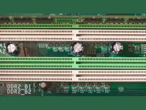
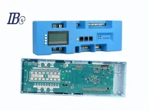
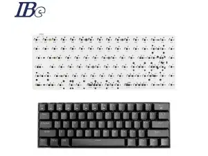
PCB design software is a suite of digital tools engineered to facilitate the creation of printed circuit boards. These software solutions cater to a wide spectrum of users, from hobbyists to professional electronic engineers, providing functionalities that streamline the PCB design process.
Why need PCB Design Software?
PCB design software plays a pivotal role in advancing electronics development:
Efficiency and Precision: These tools streamline the design process, reducing design iterations and errors while enabling precise component placement and trace routing.
Innovation and Iteration: Engineers can experiment with different design iterations, explore new concepts, and refine designs quickly, fostering innovation and product improvement.
Simulation and Validation: Simulations help predict how the PCB will perform before production, ensuring functionality, reliability, and compliance with design specifications.
Collaboration and Documentation: Software tools facilitate collaboration among teams and generate comprehensive documentation essential for manufacturing and assembly.

What are included in PCB design software?
PCB (Printed Circuit Board) design involves various components that collectively contribute to the creation of a functional and efficient circuit. These components encompass both physical and digital elements crucial for the board’s functionality and manufacturability:
Schematic Diagram: A graphical representation of the circuit design that shows the connections between components. It serves as the blueprint for the PCB layout.
Components: Electronic parts that constitute the circuit, including resistors, capacitors, inductors, integrated circuits (ICs), connectors, diodes, transistors, and more. Each component is chosen based on its function, size, and electrical characteristics.
Footprints: Physical layouts or patterns of components that indicate their placement and orientation on the PCB. Footprints are specific to each component type and are designed to accommodate the physical dimensions and soldering requirements.
Netlist: A list of interconnected nodes in the circuit, showing how components are electrically connected. It serves as a guide for creating electrical connections between components on the PCB layout.
Routing: The process of creating copper traces to establish electrical connections between components. Routing involves designing the pathways that carry electrical signals, considering signal integrity, impedance control, and minimizing interference.
Layers: PCBs are often composed of multiple layers (signal layers, power planes, ground planes) to accommodate complex circuits. Each layer carries specific signals or serves a dedicated purpose, like power distribution or electromagnetic shielding.
Design Rules and Constraints: Parameters and specifications that govern the PCB design, including trace width, clearance, via types, and other manufacturing considerations. Adhering to these rules ensures manufacturability and reliability.
Gerber Files: Standard file formats used in PCB fabrication that contain information about copper layers, solder mask, silkscreen, and other PCB manufacturing details.
Software Tools: Specialized software like Altium Designer, KiCad, Eagle, OrCAD, and others used to create schematics, generate layouts, perform simulations, and generate manufacturing files for the PCB.
Documentation: Detailed documentation that accompanies the PCB design, including assembly drawings, bill of materials (BOM), fabrication files, and assembly instructions. Clear documentation is crucial for manufacturing and assembly.
Each of these components plays a vital role in the overall PCB design process, contributing to the functionality, reliability, and manufacturability of the final printed circuit board.
What are the common used PCB design software?
Altium Designer
Website: https://www.altium.com/altium-designer
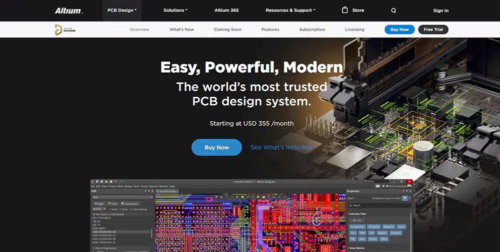
Altium Designer is a professional PCB design software known for its comprehensive suite of tools and user-friendly interface. It’s widely used in the electronics industry for creating schematics, designing PCB layouts, and preparing designs for manufacturing.
Key Features:
Unified Environment: Altium provides an integrated platform for all stages of PCB design, from schematic capture to layout, simulation, and production preparation.
Schematic Editor: Offers a robust environment for creating and editing schematic diagrams. Components are easily placed, connected, and annotated within the editor.
PCB Layout: Allows users to design PCB layouts with ease, providing tools for routing traces, placing components, defining board shapes, and creating multi-layer designs.
3D Visualization: Enables users to visualize PCB designs in 3D, helping to identify potential clashes and ensure accurate component placements.
Simulation and Analysis: Provides simulation capabilities for signal integrity, power integrity, and thermal analysis, allowing designers to validate their designs before prototyping.
Library Management: Offers a library of components and footprints and allows users to create and manage their libraries efficiently.
Manufacturing Output: Generates manufacturing-ready outputs, including Gerber files, bill of materials (BOM), assembly drawings, and documentation required for fabrication.
Benefits:
User-Friendly Interface: Altium’s intuitive interface makes it accessible to beginners while offering advanced features for experienced users.
Comprehensive Toolset: The software’s wide range of tools covers various aspects of PCB design, reducing the need for additional software.
Collaboration: Altium allows for easy collaboration among team members, facilitating concurrent design work and version control.
Community and Support: Users can benefit from a vibrant community, forums, and extensive documentation for learning and troubleshooting.
Who Uses Altium Designer?
Altium Designer is used by electronic engineers, PCB designers, hobbyists, and professionals working on various electronic products, from consumer electronics to aerospace and automotive industries.
Conclusion
Altium Designer’s powerful suite of tools, ease of use, and comprehensive capabilities make it a popular choice among PCB designers, enabling them to create high-quality, manufacturable designs efficiently.
Cadence Allegro
Website: https://www.cadence.com/en_US/home/tools/pcb-design-and-analysis/pcb-layout/allegro-pcb-designer.html

Cadence Allegro is a powerful and widely used PCB design software renowned for its robust suite of tools tailored for complex board designs. It provides an integrated platform for designing, simulating, and verifying high-performance PCB layouts.
Key Features:
Schematic Capture: Allegro offers a feature-rich environment for creating and editing schematic diagrams. Users can easily place components, connect nets, and annotate designs.
Layout Editor: The software provides advanced tools for PCB layout design, allowing users to define board shapes, place components, route traces, and manage multiple layers effectively.
Constraint Management: Allegro facilitates the management of design constraints, including signal integrity, electrical rules, and manufacturing specifications, ensuring design compliance.
3D Visualization and MCAD Integration: Enables 3D modeling and integration with mechanical design software for accurate visualization and collision detection.
Simulation and Analysis: Provides simulation capabilities for signal integrity, power integrity, thermal analysis, and electromagnetic interference (EMI), allowing users to verify design performance.
Library Management: Offers extensive libraries for components, footprints, and models, with tools to create and manage custom libraries efficiently.
Manufacturing Outputs: Generates production-ready outputs, including Gerber files, assembly drawings, bill of materials (BOM), and documentation required for fabrication.
Benefits:
High Performance: Allegro is optimized for high-complexity designs, making it suitable for projects requiring advanced functionalities and extensive rule management.
Integration: It seamlessly integrates with other Cadence tools, providing a complete electronic design automation (EDA) environment.
Collaboration and Scalability: Supports team collaboration, allowing multiple users to work on a design concurrently, and scales effectively for small to enterprise-level projects.
Comprehensive Design Verification: Offers advanced simulation and analysis tools to verify design functionality, ensuring high-quality and reliable PCB layouts.
Who Uses Altium Designer?
Cadence Allegro is primarily used by electronic engineers, PCB designers, and design teams working on intricate and high-speed electronic products across various industries, including aerospace, telecommunications, and industrial electronics.
Conclusion
Cadence Allegro’s comprehensive toolset, advanced features, and scalability make it a preferred choice for professionals dealing with complex PCB designs. It facilitates the creation of high-quality layouts while providing robust verification and simulation capabilities.
KiCad
Website: https://www.kicad.org/
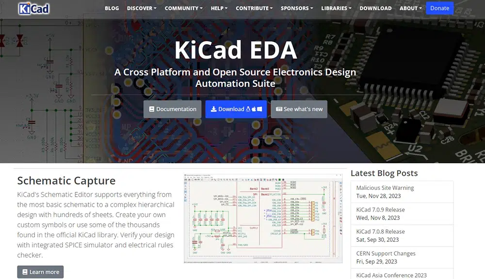
KiCad is an open-source, cross-platform software suite used for designing electronic schematic diagrams and printed circuit boards (PCBs). Developed by the KiCad Developers Team, it offers a comprehensive set of tools tailored for electronics design.
Key Features:
Schematic Capture: KiCad provides an intuitive environment for creating and editing electronic schematic diagrams. Users can place components, connect nets, and annotate designs efficiently.
PCB Layout: Its layout editor enables users to design PCBs, define board shapes, place components, route traces, manage layers, and create custom footprints for components.
3D Viewer: KiCad includes a 3D viewer that allows users to visualize their PCB designs in a three-dimensional space, aiding in component placement and checking for clearances.
Library Management: Offers a library manager to handle components, footprints, and symbols. Users can create custom libraries or import existing ones for reuse.
Gerber File Generation: Supports generating Gerber files, essential for PCB manufacturing, as well as other output formats like BOM (Bill of Materials) and assembly drawings.
Community and Support: Being open-source, KiCad benefits from a vibrant user community that provides support, tutorials, and additional libraries to enhance the software’s capabilities.
Benefits:
Free and Open-Source: KiCad is freely available, making it accessible to hobbyists, students, and professionals without licensing costs.
Cross-Platform Compatibility: It runs on multiple operating systems, including Windows, macOS, and Linux, ensuring flexibility for users on different platforms.
Extensible and Customizable: Users can extend its functionality by developing plugins or utilizing additional tools offered by the community.
Schematic Symbol and Footprint Editor: KiCad includes tools to create custom symbols and footprints, allowing for flexibility in design components.
Who Uses Altium Designer?
KiCad is used by hobbyists, makers, students, and professional engineers involved in electronics design, prototyping, and small-scale production across various industries.
Conclusion
KiCad offers a robust set of features for electronic design, making it a popular choice among users seeking a free and open-source solution for schematic capture and PCB layout. Its active community support, regular updates, and versatile tools make it a competitive option for projects of varying complexities.
Eagle PCB
Website: https://www.autodesk.com/products/eagle/overview?term=1-YEAR&tab=subscription
Eagle PCB is a widely used software suite developed by CadSoft, now part of Autodesk. It serves as a comprehensive solution for designing electronic schematics and PCB layouts. Eagle offers a range of tools catering to different skill levels, from beginners to experienced engineers.
Key Features:
Schematic Editor: Eagle provides an intuitive interface for creating and editing electronic schematics. Users can add components, connect nets, and define relationships between elements.
PCB Layout Editor: Its layout editor allows users to design PCBs by placing components, routing traces, defining layers, and ensuring design rule checks for error-free designs.
Component Library: Eagle comes with a vast library of components and footprints, and it allows users to create their own custom libraries for reuse in projects.
3D Visualization: It offers a 3D viewer that allows users to visualize their PCB designs in a three-dimensional space, aiding in component placement and detecting potential issues.
Design Rule Checking: Eagle includes tools to perform design rule checks to ensure the design complies with specific constraints and requirements.
CAM Processor: Supports generating manufacturing files like Gerber files, drill files, and bill of materials (BOM), essential for PCB fabrication.
Community and Support: Eagle has a supportive user community offering tutorials, forums, and resources, aiding users in learning and problem-solving.
Benefits:
User-Friendly Interface: Eagle provides an easy-to-use interface, making it suitable for both beginners and advanced users.
Extensive Libraries: The software includes a vast library of components and footprints, reducing the time required for component creation.
Cross-Platform Compatibility: It is available for Windows, macOS, and Linux, ensuring accessibility across various operating systems.
Customization: Users can create custom libraries, components, and scripts to extend Eagle’s capabilities and tailor it to their specific project needs.
Who Uses Altium Designer?
Eagle PCB is used by hobbyists, makers, students, and professionals working in electronics design, prototyping, and small-scale production across diverse industries.
Conclusion
Eagle PCB is a widely adopted software suite for electronic design due to its user-friendly interface, extensive component library, and versatile tools for both schematic capture and PCB layout. It caters to a broad spectrum of users, from enthusiasts to professionals, making it a popular choice for a range of electronic design projects.
OrCAD
Website: https://www.cadence.com/en_US/home/tools/pcb-design-and-analysis/orcad.html
OrCAD, developed by Cadence Design Systems, is a comprehensive suite of electronic design automation (EDA) tools catering to schematic capture, simulation, and PCB layout design. It’s a highly regarded software used in the electronics industry for its robust capabilities and user-friendly interface.
Key Features:
Schematic Capture: OrCAD offers an intuitive environment for creating electronic schematics, enabling users to place components, connect nets, and define relationships between elements seamlessly.
Simulation Capabilities: It includes powerful simulation tools for analog, digital, and mixed-signal simulations, allowing users to verify circuit behavior before the PCB layout phase.
PCB Layout Design: OrCAD facilitates the design of PCB layouts by enabling users to place components, route traces, define layers, and perform design rule checks (DRC) for error detection.
Library Management: It provides a vast library of components and footprints, and users can create custom libraries or modify existing ones to suit their project requirements.
Signal Integrity Analysis: OrCAD allows for signal integrity analysis to ensure proper signal transmission and reduce issues like reflections, noise, and timing violations.
Manufacturing Outputs: The software generates essential manufacturing files, such as Gerber files, NC drill files, and bill of materials (BOM), necessary for PCB fabrication and assembly.
Collaborative Environment: OrCAD supports collaboration among team members by allowing multiple users to work on a project simultaneously.
Benefits:
Comprehensive Toolset: OrCAD offers a comprehensive set of tools for the entire electronic design process, from schematic capture to PCB layout and manufacturing.
Simulation Capabilities: Its simulation features enable users to predict circuit behavior accurately, reducing the need for physical prototypes and saving time and resources.
Extensive Libraries: The software includes a vast component library and allows customization, minimizing the effort required for creating and managing components.
Reliability and Accuracy: OrCAD’s design rule checks and simulation capabilities ensure the accuracy and reliability of the final design, reducing errors in the manufacturing stage.
Who Uses Altium Designer?
OrCAD is widely used by electronics engineers, PCB designers, hobbyists, and students involved in designing electronic circuits, from small-scale projects to complex systems, across industries like aerospace, automotive, consumer electronics, and more.
Conclusion
OrCAD stands out in the realm of electronic design software due to its robust features, simulation capabilities, and comprehensive tools for schematic capture, PCB layout, and analysis. It remains a popular choice for electronics design, offering a seamless design flow and reliable performance, suitable for a wide range of design projects.
Conclusion
PCB design software serves as a cornerstone in modern electronics, empowering designers and engineers to create sophisticated, efficient, and reliable printed circuit boards. With its diverse functionalities, ease of use, and capabilities for innovation and validation, PCB design software continues to be indispensable in shaping the future of electronic devices and technology.
Altium Designer
Cadence Allegro
KiCad
Eagle PCB
OrCAD
Altium Designer is a professional printed circuit board (PCB) design software known for its comprehensive suite of tools and user-friendly interface. It's widely used in the electronics industry for creating schematics, designing PCB layouts, and preparing designs for manufacturing.
Cadence Allegro is a powerful and widely used printed circuit board (PCB) design software renowned for its robust suite of tools tailored for complex board designs. It provides an integrated platform for designing, simulating, and verifying high-performance PCB layouts.

