With the continuous advancement of electronic technology, the application field of high-speed PCB and low-speed PCB continues to expand. In terms of PCB manufacturing and PCB design, these two different printed circuit boards require different manufacturing processes and design techniques. In today’s high-speed era, with the increase in the switching speed of integrated circuit output, the speed of many devices has reached the picosecond level.
Therefore, the definition standards for high-speed circuit boards and low-speed circuit boards have become a concern for manufacturers and designers. Next, we will introduce in detail the defining criteria for high-speed and low-speed PCBs.

The definition of high-speed PCB and low-speed PCB
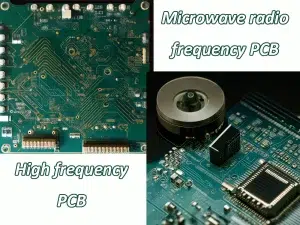
High-speed PCB refer to boards that operate at high frequencies and high speeds, such as DDR3, DDR4, PCIE and other common applications.
Low-speed PCB refer to circuit boards that work at low frequencies and low speeds, such as single-chip microcomputer development boards, household appliance control boards, etc.
The misunderstandings between high-speed and low-speed PCB design
1: A high signal cycle frequency FCLOCK is a high-speed design
A high-speed design is a high-speed design with a high signal period frequency
The highest frequency considered in the design often depends on the effective frequency of the signal (also known as the corner frequency) Fknee
The signal period frequency and the effective (corner) frequency are defined as:
FCLOCK Tclock = 1/(10% 90%) 0.5/ Fknee = Tr − (for most signals)
2: Capacitors and inductors are ideal devices
In the low-speed field, capacitors and inductors operate in relatively low frequency bands, which can be considered ideal devices. However, in the high-speed field, Capacitors and inductors , etc. on PCBs can no longer be simply regarded as pure Capacitors and inductors .
For low-speed signals, the level of points on the transmission path is approximately the same, and we can adopt lumped thinking to treat the transmission path, that is, the state of each point on the transmission path is the same; For high-speed signals, the levels of each point on the transmission path are different, and distributed thinking needs to be adopted, that is, the state of each point is different. Therefore, the distinction between high speed and low speed also depends on the length of the signal transmission path.
The difference between high-speed PCB and general PCB
Design of high-speed PCB and general PCB are two different circuit board designs, and their design goals and requirements are different, so different methods and technologies need to be taken in the design and manufacturing process. The following is the difference between high-speed PCB and general PCB and its impact.
The frequency and transmission speed of high-speed signals
The signal frequency and transmission speed in high-speed PCB designs are usually higher than those of ordinary PCBs, which means that in high-speed PCB design, signal integrity and anti-interference capabilities need to be considered to ensure accurate transmission and reception of signals. This requires a range of design and manufacturing techniques, such as signal integrity analysis, simulation, optimized layout, and cabling.
Line width and spacing requirements
In high-speed PCB design, linewidth and spacing requirements are usually more stringent than those of ordinary PCBs. This is because the transmission of high-speed signals requires smaller linewidths and smaller spacing to reduce signal propagation delay and cross-interference. In addition, it is necessary to pay attention to the distance between the signal and the ground in order to reduce the noise and distortion of the signal.
Choice of PCB material
High-speed PCB design often requires the use of high-performance PCB materials, such as high-frequency organic materials, PTFE, and composite materials. These materials have a low dielectric constant and dielectric loss, which can reduce the propagation delay and noise of the signal. In addition, it is necessary to pay attention to the coefficient of thermal expansion and temperature stability of the material to ensure stable performance of the circuit board in high temperature and humidity environments.
Optimization of PCB layout and wiring
In high-speed PCB design, optimization of layout and wiring is very important. Factors such as the transmission path of the signal, the routing method of the signal, the layout of the power supply and ground wire, etc. need to be considered to ensure the integrity of the signal and the ability to resist interference. In addition, there are some rules to follow when laying out and wiring, such as avoiding sharp angles and reducing the impedance of power and ground.
High-speed PCB needs to pay attention to impedance control of the signal line, high-speed signal line does not do a good job of impedance matching may cause signal reflection, loss, deformation, etc., resulting in unsatisfactory circuit performance or even can not achieve the required functions. In high-speed PCB routing, the trace impedance of the digital signal is generally designed to be 50 ohms, which is an approximate number.
In summary, there are big differences between high-speed PCBs and general PCBs in the design and manufacturing process. High-speed PCBs need to consider factors such as signal integrity, linewidth and spacing, material selection, layout, and wiring to ensure accurate signal transmission and reception. Therefore, when designing high-speed PCBs, professional design and manufacturing techniques are required to ensure the performance and reliability of the circuit board.
The definition standards of high-speed PCB and low-speed PCB
The definition criteria for high-speed PCB and low-speed PCB mainly depend on parameters such as signal clock frequency, signal transmission rate, and signal rising and falling edge times. Specifically, it can be judged based on the following four parameters:
1. Signal clock frequency: When the working frequency of the circuit board is greater than 50MHz, it is generally considered to be a high-speed circuit board; When the circuit board operating frequency is less than 50MHz, it is generally considered to be a low-speed circuit board.
2. Signal transmission rate: When the signal transmission rate exceeds 1Gbps, it can be considered as a high-speed circuit board; When the signal transmission rate is less than 1Gbps, it can be considered a low-speed circuit board.
3. Signal rising/falling time: signal rising /falling time is an important factor affecting the signal transmission rate, when the signal rising/falling time is less than 500ps, it can be considered as a high-speed circuit board, if greater than 500ps, it is considered to be a low-speed circuit board.
4.Signal integrity: High-speed PCB are prone to signal distortion problems during signal transmission, which requires that the design and manufacture of high-speed circuit boards must have higher accuracy and stability.
Conclusion
Through the above analysis, we can conclude that the definition standards of high-speed PCB and low-speed PCB mainly depend on parameters such as signal clock frequency, signal transmission rate, signal rising edge and falling edge time, etc. When designing and manufacturing high-speed circuit boards, it is necessary to pay attention to signal integrity issues and improve the accuracy and stability of the circuit board. In practical applications, design and manufacture according to defined standards as much as possible to ensure the stability and reliability of the circuit board.
In short, the definition standards of high-speed circuit boards and low-speed circuit boards is an important issue that needs to be discussed and solved by circuit board manufacturers and designers. Only by mastering the defining standards for high-speed circuit boards and low-speed circuit boards can we better meet the various challenges encountered in board manufacturing and design. It is believed that with the continuous advancement of technology, the design and manufacturing level of high-speed circuit boards and low-speed circuit boards will continue to improve, providing better support and guarantee for the development and application of electronic technology.

