In today’s fast-paced world, where precision, reliability, and miniaturization are paramount, one groundbreaking technique stands out: Surface Mount Technology (SMT). This innovative method has transformed the electronics manufacturing industry over the past few decades, offering a way to achieve compact designs without compromising performance. In this article, we will delve into the world of SMT, exploring its definition, widespread adoption, advantages and disadvantages, and the intricacies of its assembly process.
What is Surface Mount Technology?
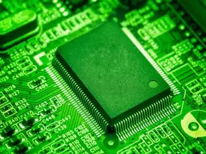
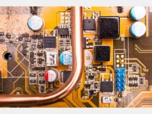
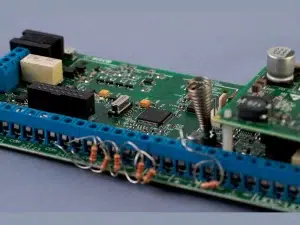
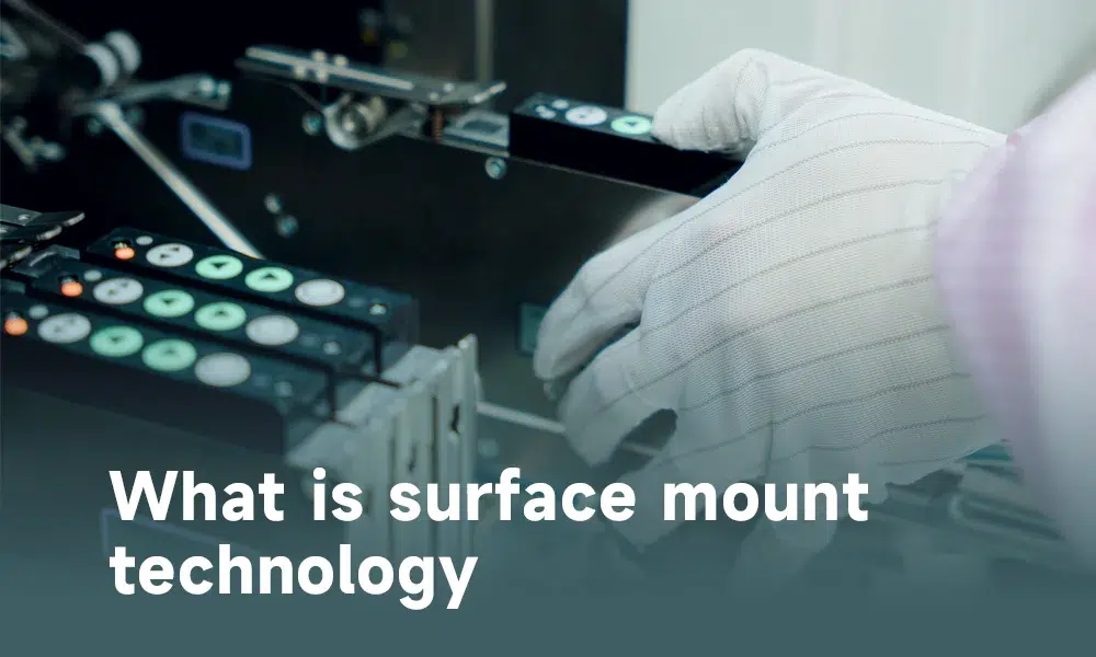
Surface mount technology involves mounting electronic components, known as Surface Mount Devices (SMDs), directly onto the surface of printed circuit boards (PCBs). Unlike traditional through-hole technology, which relies on component leads inserted into drilled holes, SMT attaches components directly to the PCB surface. By eliminating the need for holes, SMT enables more efficient and compact circuit designs. Although invented in the 1960s, SMT gained significant popularity in the 1990s and has now become a standard practice in electronics manufacturing.
Why is SMT used?
The primary driving force behind the widespread adoption of SMT is its exceptional efficiency. By allowing the mounting of more components in less space, SMT enables the miniaturization of electronic devices without compromising their performance. Moreover, the elimination of drilling operations reduces assembly time, and automated assembly processes become feasible. The result is higher component density, improved performance, and reduced production costs.
In the era of smartphones, laptops, wearables, and other compact electronic devices, SMT has emerged as the unsung hero, empowering engineers to integrate an astonishing number of components onto a single circuit board. Furthermore, SMT has enhanced production efficiency and lowered manufacturing costs, making it the preferred choice for mass-produced electronics.
What are the advantages and disadvantages of SMT ?
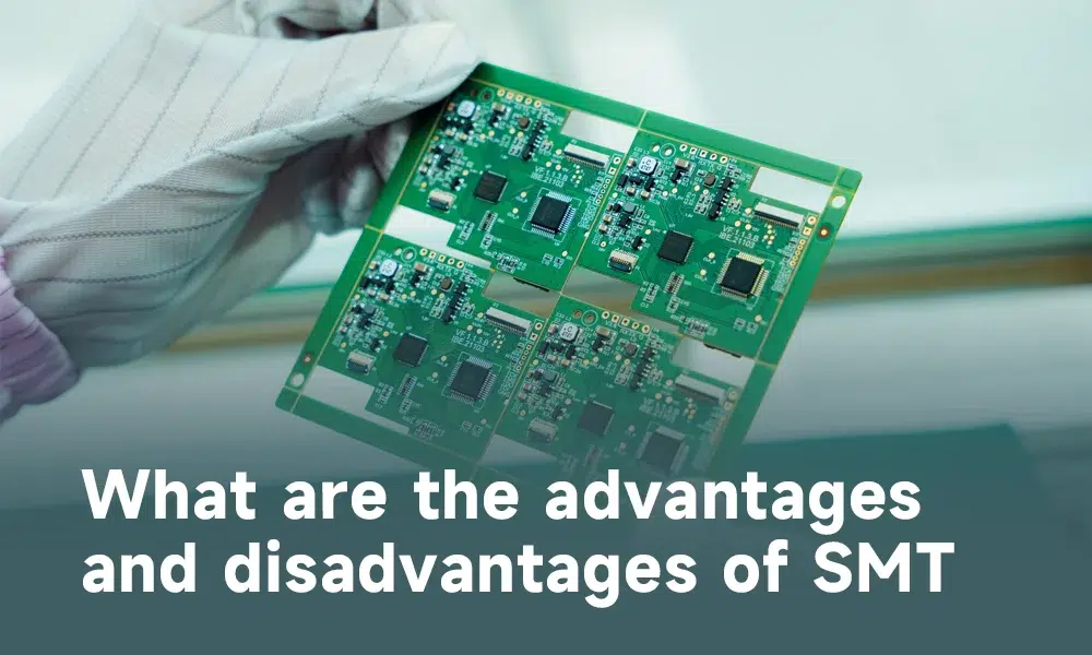
Like any technology, SMT comes with its own set of advantages and disadvantages. On the positive side, SMT enables higher component density and greater complexity in a smaller space. It also provides excellent mechanical and electrical properties, and its automated assembly processes lead to higher production rates and lower costs. Additionally, SMT is compatible with most modern electronic components, accommodating both simple and complex circuit designs.
However, SMT does present challenges. The small size of SMT components can make manual assembly and repair difficult. SMT boards are more susceptible to damage from shock or vibration compared to through-hole boards, and their assembly requires more sophisticated and expensive equipment. Precise component placement is critical, necessitating advanced machinery. Moreover, SMT components are susceptible to thermal stress during soldering, and reworking faulty parts can be challenging due to their tiny size and close proximity to other components.
How is surface mount technology made?
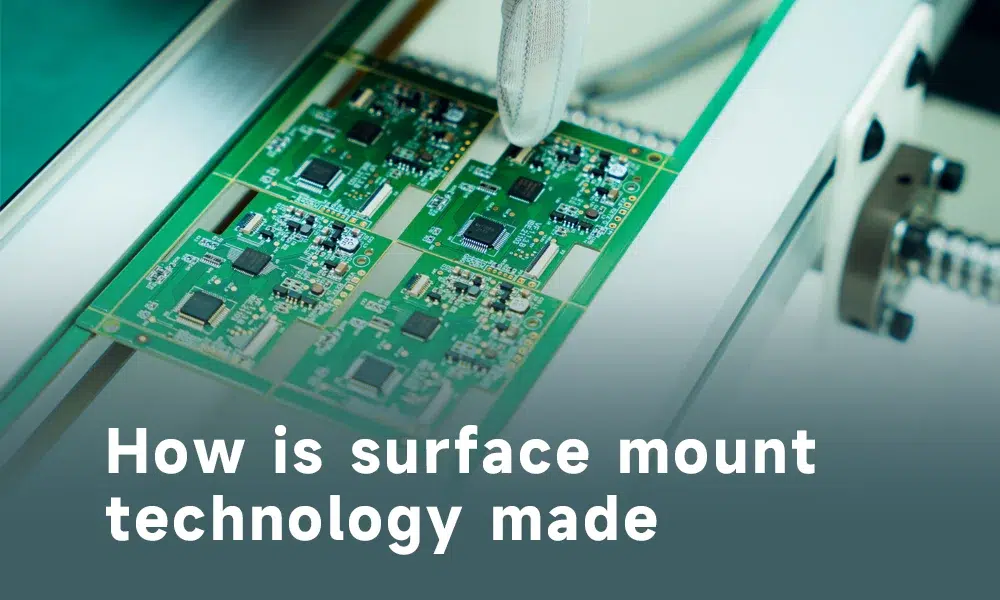
The assembly process using SMT involves several essential steps.
1.Firstly, a solder paste, which acts as both an adhesive and a medium for electrical connectivity, is applied to the designated areas of the PCB using a stencil and a squeegee. This paste serves as the foundation for component placement.
2.Next, the components are precisely positioned onto the solder paste using a pick-and-place machine. Equipped with a vacuum grip, this machine carefully picks up the components and places them onto the predetermined positions on the board.
3.The subsequent phase is reflow soldering, where the entire assembly is heated in a reflow oven. The heat causes the solder paste to melt and then solidify as it cools, establishing mechanical and electrical connections between the components and the PCB.
4.Finally, the assembled PCB undergoes inspection for potential defects, and any necessary rework is performed to ensure optimal functionality.
What is SMT material?
Surface mount technology materials encompass various components used in the SMT assembly process. These include the solder paste, printed circuit boards (PCBs), Surface Mount Devices (SMDs), and other auxiliary materials such as flux, adhesives, and cleaning agents.
What is the difference between SMT and SMD?
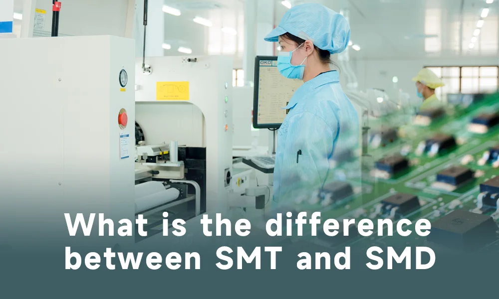
Surface Mount Technology (SMT) and Surface Mount Devices (SMDs) play key roles in the assembly of electronic circuits. Here’s a concise breakdown of their differences:
SMT:
●Refers to the process of mounting and soldering components onto a Printed Circuit Board (PCB).
●Accommodates miniaturization of electronic devices and is widely used in high-volume production.
●Involves steps like applying solder paste, precise component placement, and heating for bonding.
●Enables complex devices with numerous components on a single PCB.
SMD:
●Are the actual components mounted on PCBs using SMT.
●Include various electronic components like resistors, capacitors, and integrated circuits.
●Feature small leads or terminals for direct soldering onto the PCB.
●Smaller, lighter, and suitable for compact electronic devices compared to Through-Hole Technology (THT) components.
In summary, SMT refers to the assembly process, while SMDs are the components used in this process. Together, they have revolutionized the electronics industry, enabling miniaturization and pushing technological boundaries.
How are SMT components soldered?
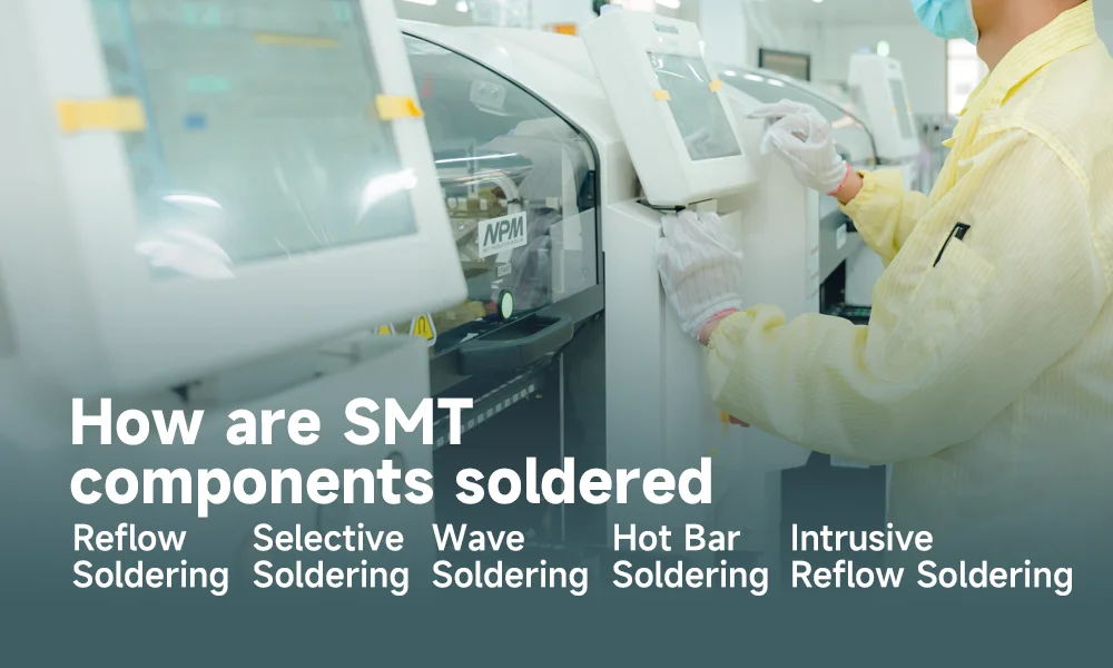
Surface Mount Technology employs several soldering methods, each with its own strengths and applications.
Reflow Soldering
The most common method is reflow soldering, which involves applying solder paste to the PCB, placing the components, and heating the assembly to melt the solder, forming mechanical and electrical bonds.
Wave Soldering
Wave soldering, on the other hand, is a bulk soldering process where the PCB is passed over a pan of molten solder, creating a ‘wave’ that solders the components in place. Reflow soldering is the more commonly used method in SMT due to its accuracy.
Wave soldering, traditionally used for through-hole component assembly, can also be employed in SMT for components capable of withstanding intense heat. The PCB, with components already in place, is passed over a wave of molten solder, creating the necessary connections. However, wave soldering is less suitable for smaller, delicate SMT components.
Selective Soldering
Selective soldering is utilized when only specific components on a PCB require soldering. This method allows for precise application of heat, safeguarding heat-sensitive components from exposure to high temperatures. Mini-waves or jets are commonly used to apply the solder to targeted areas.
Hot Bar Soldering
Hot bar soldering is often used for components with larger soldering areas, such as connectors or larger surface-mount components. This technique involves pressing a heated bar onto the area to be soldered, melting the solder, and subsequently creating a bond as it cools and solidifies.
Intrusive Reflow Soldering
Intrusive reflow soldering, also known as pin-in-paste soldering, combines aspects of both SMT and through-hole soldering. It entails applying solder paste into the holes of the PCB and then inserting the component leads into the paste-filled holes. The assembly is subsequently passed through a reflow oven, resulting in a bond similar to traditional through-hole soldering but with the time efficiency of SMT.
Each of these methods has its strengths and applications, and the choice of soldering method depends on the requirements of the specific electronic assembly, including the type of components used, the complexity of the PCB, and the desired production speed and efficiency. With the right soldering method, SMT can achieve high production rates while maintaining the quality and reliability of the electronic assembly.
What is the machine used in SMT?
Among the various machines employed in the SMT assembly process, the pick-and-place machine is the most crucial. This automated device significantly enhances efficiency and accuracy by precisely placing SMDs onto the PCB. Additional equipment includes the stencil printer, which applies solder paste, and the reflow oven, responsible for soldering the components to the PCB.

Final Thoughts
Surface Mount Technology has become a cornerstone of the modern electronics industry, enabling the miniaturization of electronic devices without compromising performance. Despite its challenges, the numerous advantages of SMT, such as higher component density and improved production efficiency, have made it the preferred choice for manufacturers. As we continue to refine this technology, we unlock new possibilities for advancements in electronics, driving our digital age forward.
FAQ about surface mount technology
Surface mount technology involves mounting electronic components, known as Surface Mount Devices (SMDs), directly onto the surface of printed circuit boards (PCBs). Unlike traditional through-hole technology, which relies on component leads inserted into drilled holes, SMT attaches components directly to the PCB surface.
Reflow Soldering
Wave Soldering
Selective Soldering
Hot Bar Soldering
Intrusive Reflow Soldering
By allowing the mounting of more components in less space, SMT enables the miniaturization of electronic devices without compromising their performance.

